Minigris test matrix

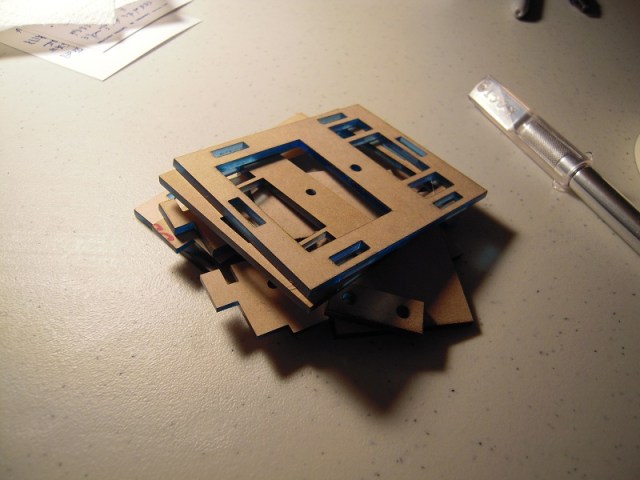
DSCN8745

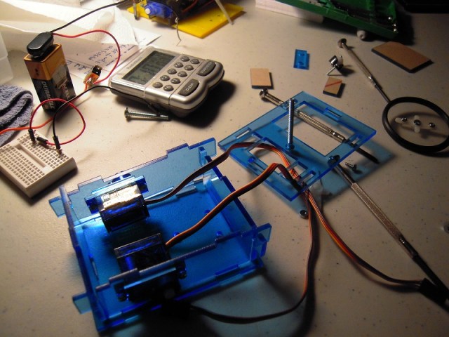
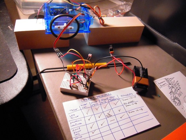
Since minigris did not perform as hoped, I’ve had to go back to basics and rebuild the circuit, testing at each stage. Hence a test matrix, where I build the circuit with a component added, write a test program, test on the Arduino (if necessary), then test the ATMega chip on battery power.

The rows are: LED blink, photocell confirm, dual photo cell, servo, 2 servo, and 2 photo cell plus 2 servo. As you can see from the check offs, I’m about halfway through. So far, everything has worked first time through. I expect that will change.

(At the time of the photo, the ATMega was on the Arduino waiting to be reprogrammed with the servo test program.)

Posted in Uncategorized | Tagged , , , | 1 Comment

AtMega Ohmmeter Designs and Auto-Off Function

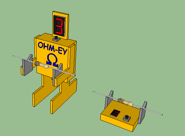
I drew up some alternative designs for the casing, like so:

resisty 2

The design on the left is a laser-cut version of the robot case. The box design on the right is the utilitarian model, of course.

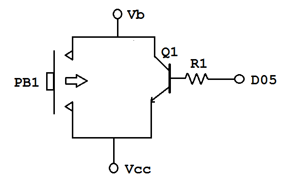
Now for the pushbutton circuit and the auto-off function:

resisty push button

When the user presses push button PB1, it allows battery power Vb to pass down to Vcc, which inputs voltage to the microcontroller and powers the microcontroller. When the microcontroller powers on, it notes the time (= tstart) and sets pin D5 in digital output mode to HIGH. This turns on transistor Q1, providing a circuit path from Vcc to Vb so that the microcontroller continues to be powered after the user releases the push button.

The microcontroller program then performs the ohmmeter measurement and display functions as described in the previous entry. While the functions are executing, the microcontroller also checks the time and compares it to the initial time tstart. When the present time is, say, thirty seconds past tstart, the program sets pin D5 to LOW, which causes transistor Q1 to turn off, which causes the circuit between Vb and Vcc to break, which causes the ohmmeter to turn off automatically.

An improvement on this might be to have the ohmmeter also turn off automatically after it has displayed the reading three times.

Another improvement would be to figure out how to activate the circuit without the need for a pushbutton.

Posted in Uncategorized | Tagged , , , | Leave a comment

ATMega Ohmmeter

As I get older, it’s harder to read the color bands on resistors, and frankly, sometimes it’s hard to tell the oranges from the yellows and reds, the greens from the blues, and even the browns from the blacks. Taking out a multimeter, setting the controls, and fumbling with the probes and resistor leads is annoying.

So I thought, what if there was a little ohmmeter where you take a resistor, lay it on a cradle, and a display instantly tells you the value?

I did a search and found that several people have done Arduino Ohmmeter projects, but the cost of a dedicated Arduino board boosts the cost over $30. What I want to do is take the ‘naked ATMega’ off the Ardruino and make an ohmmeter that would cost less than ten dollars.

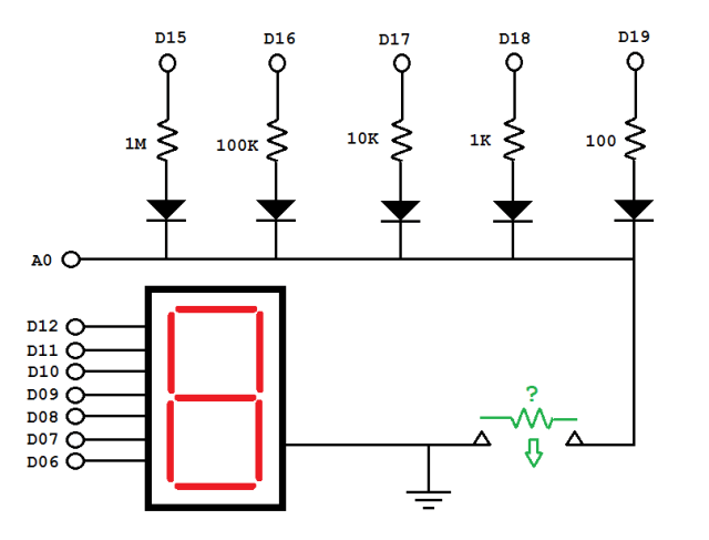
Realizing that analog input pins can be programmed as digital output pins (ie, D15 = A1, D16 = A2, etc.), I made the following schematic:

resisty

Here’s how it works. The resistor is placed across the terminals on the lower right. I envision a cradle for the resistor, and a pushbutton (not shown) activates the circuit. The microcontroller then puts a voltage on D15 which passes through the one mega ohm resistor, the diode, and then the unknown resistor. The voltage is read at A0.

If the reading at A0 is below 100 (on a scale of 0-1000 units corresponding to 0-5 volts), D15 switches off and D16 switches on. Now the voltage divider is through a 100K resistor. If the reading at A0 is still below 100, we switch to D17 and a 10K resistor, and so on, until we get a reading above 100 or until we get to D19.

At that point, using a formula that I need to work out (which may involve dealing with the internal resistance at A0), the microcontroller calculates the unknown resistance.

To save money, the output is a single 7-segment LED display. I figure the display will flash three numbers in sequence and mimic the bands on a resistor: first digit is first significant number, second is second, third is how many zeros. Thus if you see 4 followed by 7 followed by 2, it means 4700 ohms. To avoid confusion, zero zeroes is represented by ‘-‘ instead of a zero.

So here is the user experience:

1. User places resistor on cradle.
2. User presses button to activate.
3. 7-seg display flashes digit 1 for one second, digit 2 for one second, digit 3 for one second, followed by 3 second pause, then repeats twice.
4. Device automatically shuts off.
5. User removes resistor from cradle.

For a ‘cuteness factor,’ maybe this could be made into a little robot figurine.

resisty robot 1

Posted in Uncategorized | Tagged , | 2 Comments

Minigris wiring revisions

gris schematic 07f

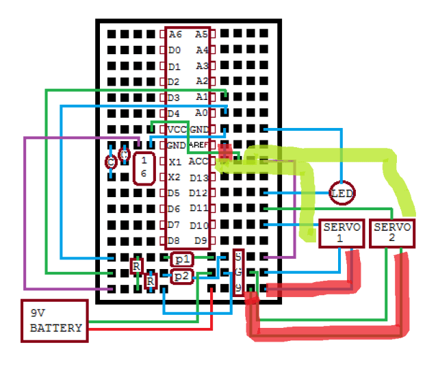
Well, I did notice that the servos were going to nine volts rather than five on yesterday’s schematic, so I fixed that. Also deleted the connection to AREF per this. But I couldn’t even get the LED to light up when I did a test of the fully assembled system. My presentation at SRS on Saturday morning was a ‘static demo,’ alas.

And in case you’re wondering, yes, I did check the battery and voltage regulator. Tomorrow I’m going to take the circuit apart completely and then build it up from the bare ATMega328 chip and support components (voltage regulator, crystal, caps, etc.). I’ll see if I can get that LED to blink, then integrate the photocells and servos. The components have worked separately in the past, and I’m confident that they can work together too.

Posted in Uncategorized | Tagged , , | 1 Comment

Mini gris on a mini breadboard

gris schematic 07c

Here is the wiring diagram for the mini gris mini breadboard. As soon as I post it, I’ll realize there’s something wrong. So we may as well get it over with.

Posted in Uncategorized | Tagged , , , , , | Leave a comment

Minigris Assembly Begins

I went to Metrix this afternoon (Thursday) and got the acrylic cut, and then I rushed home and attempted to assemble the robot. Here are the pieces with the protective wrapping still on them:

DSCN8501

Ten minutes later, I’m still peeling off the wrapping:

DSCN8502

Whew, glad that’s done. Twenty minutes into the game, it was onto the servos:

DSCN8503

This is where that assembly illustration that I made earlier came in useful (30 min.):

DSCN8504

After forty minutes, it’s fully assembled:

DSCN8507

Well, except for the wires. I have to figure out how to rearrange the wires to free up space on the breadboard to attach both the servos and the photocells. As I contemplate how to untangle that, I realize that my demo at SRS on Saturday may only be a static display . . . .

Posted in Uncategorized | Tagged , , | Leave a comment

Grisbot test rig

DSCN8374

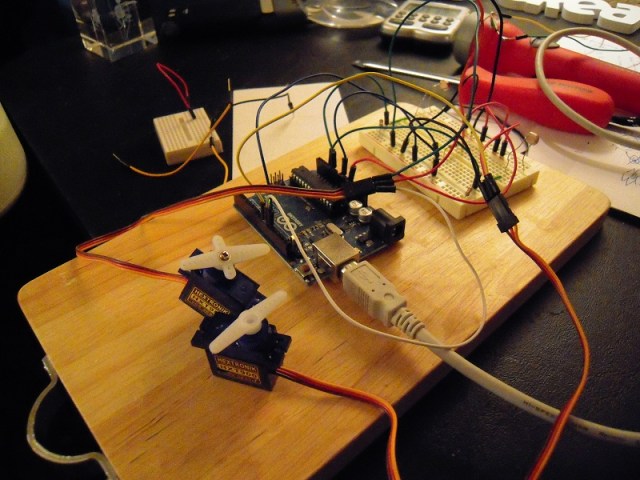
When I finished assembling this test rig on late Tuesday night, I sat back and stared and realized that maybe I’ve actually accomplished something. Such a weird feeling!

The test rig is mounted on a small kitchen chopping board that I got at Goodwill and normally use for soldering on top of so that I don’t get solder on the work table. Now it’s been pressed into service as a test rig platform.

Going from lower left to upper right: micro servos, Arduino, photocells.

I’ll test it this morning and if it passes, the cutting of the acrylic will occur at Metrix by afternoon and by Saturday I’ll be doing a demo at the Seattle Robotics Society meeting.

Happy 1728!

Posted in Uncategorized | Tagged , , , | Leave a comment

PC to Arduino to LED Control, Source Code

Due to popular demand, here is the source code for my blog entry, “PC to Arduino to LED Control.”

First the Processing Source code:


// ButtonProc
// Make a button on the screen that can be clicked
// and cause an LED to turn on and off in synch on 
// the Arduino.  Used in conjunction with ButtonArd.
// 

import processing.serial.*;

Serial myPort;  // Create object from Serial class
int val;        // Data sent to the serial port


  // set ButtonValueY = 0
    int ButtonValueY = 0;
    int ButtonValueR = 0;
    int ButtonValueG = 0;
    int ButtonValueB = 0;
    
  // set clickflag = 0
    int clickflag = 0;
    
void setup() {
  size(480, 500);
  smooth();
 
 String portName = Serial.list()[0];
  myPort = new Serial(this, portName, 9600);
  
 fill(150,150,0);
  rect(100, 100, 50, 50);
  fill(150,0,0);
   rect(100,200, 50,50);
   fill(0,150,0);
  rect(100,300,50,50);
  fill(0,0,150);
  rect(100,400,50,50);

    }

void draw() {

  // IF the mouse not pressed
  // THEN clickflag = 0 and return
  
     if (mousePressed) {
       clickflag = 0;
     return;
     }

  
  //for when the mouse is pressed:
  // IF clickflag = 1 
  // THEN return
  
    if (clickflag == 1) 
    {
      return;
    }
    
   // for the first time that we read the button is pressed:
   // clickflag = 1
   
   clickflag = 1;
   

  // Yellow LED:  Is MouseX and MouseY within boundaries?  
        if ((mouseX > 100) && (mouseX < 150) && (mouseY > 100) && (mouseY < 150)) 
       {
           // Is ButtonValueY = 0?
          if (ButtonValueY == 0) {
              ButtonValueY = 1;
              fill(255,255,0);
              myPort.write('A');
              rect(100, 100, 50, 50);
          } else {  
             fill(150,150,0);
             ButtonValueY = 0;
             myPort.write('B');
             rect(100, 100, 50, 50);           
          } // end of ButtonValueY check
          
          }
         
          
  // Red LED:  Is MouseX and MouseY within boundaries?  
        if ((mouseX > 100) && (mouseX < 150) && (mouseY > 200) && (mouseY < 250)) 
       {
           // Is ButtonValueR = 0?
          if (ButtonValueR == 0) {
              ButtonValueR = 1;
              fill(255,0,0);
              myPort.write('C');
              rect(100, 200, 50, 50);
          } else {  
             fill(150,0,0);
             ButtonValueR = 0;
             myPort.write('D');
             rect(100, 200, 50, 50);           
          } // end of ButtonValueR check  
          }  
    
  // Green LED:  Is MouseX and MouseY within boundaries?  
        if ((mouseX > 100) && (mouseX < 150) && (mouseY > 300) && (mouseY < 350)) 
       {
           // Is ButtonValueG = 0?
          if (ButtonValueG == 0) {
              ButtonValueG = 1;
              fill(0,255,0);
              myPort.write('E');
              rect(100, 300, 50, 50);
          } else {  
             fill(0,150,0);
             ButtonValueG = 0;
             myPort.write('F');
             rect(100, 300, 50, 50);           
          } // end of ButtonValueG check  
          }       
     
      // Blue LED:  Is MouseX and MouseY within boundaries?  
        if ((mouseX > 100) && (mouseX < 150) && (mouseY > 400) && (mouseY < 450)) 
       {
           // Is ButtonValueB = 0?
          if (ButtonValueB == 0) {
              ButtonValueB = 1;
              fill(0,0,255);
              myPort.write('G');
              rect(100, 400, 50, 50);
          } else {  
             fill(0,0,150);
             ButtonValueB = 0;
             myPort.write('H');
             rect(100, 400, 50, 50);           
          } // end of ButtonValueG check  
          }          


}


And here is the Arduino source code:

int incomingByte = 0;	// for incoming serial data

void setup() {
	Serial.begin(9600);	// opens serial port, sets data rate to 9600 bps
        // initialize the digital pin as an output.
        pinMode(13, OUTPUT);
        pinMode(12, OUTPUT);
        pinMode(11, OUTPUT);
        pinMode(10,OUTPUT);
        
}

void loop() {

	// act on data only when you receive data:
	if (Serial.available() < 1) {
          return;
          }
        
	// read the incoming byte:
	incomingByte = Serial.read();

        //yellow LED   
	if (incomingByte == 65){
          digitalWrite(13, HIGH);   // set the LED on
          }               
        if (incomingByte == 66) {
          digitalWrite(13, LOW);   // set the LED off
        }  
          

        //red LED           
	if (incomingByte == 67) {
          digitalWrite(12, HIGH);   // set the LED on
          } 
              
        if (incomingByte == 68) {
          digitalWrite(12, LOW);   // set the LED off
          } 

        //green LED           
	if (incomingByte == 69) {
          digitalWrite(11, HIGH);   // set the LED on
          } 
              
        if (incomingByte == 70) {
          digitalWrite(11, LOW);   // set the LED off
          }  
          
        //blue LED           
	if (incomingByte == 71) {
          digitalWrite(10, HIGH);   // set the LED on
          } 
              
        if (incomingByte == 72) {
          digitalWrite(10, LOW);   // set the LED off
          }            

	
}

You should be able to copy and paste this into the Processing and Arduino IDEs without any trouble. I’ll try to provide support, but I apologize in advance for being distracted with other stuff at the moment.

Posted in Uncategorized | Tagged , , , | 3 Comments

Robot assembly order is important

When I attempted to assemble the first laser-cut casing for grisbot, it was a learning experience. In particular I learned that design has to accommodate the assembly process. So that’s what I’m trying to anticipate with minigris.

mga-1a

For example, in the above illustration we see that the servo wires won’t fit through the hole if we try to insert the servo from the exterior of the side panel. So we have to insert the servo from the interior, and only then can we attach the wheel.

mga-1b

Here I’m using the bottom panel as the assembly base, logically enough. Thus I begin by inserting the rear panel.

mga-2a

Since the rear panel has slots pointing upward, it’s easy to ‘hook’ the side panels onto the assembly. Contrast with my previous grisbot design, which had side tabs and slots requiring all four vertical-oriented pieces to be fitted together at once and only then attached to the base. That was a challenge to my lack of manual coordination!

mga-2b

The slots on the front panel point downward, which enables the front panel to be easily removed. I’m planning to offer optional equipment that can be installed into the empty space under and forward of the servos, and having an easily-removed-and-reinstalled front panel facilitates that.

I learned from my previous design that servo wires take up a lot of room internally and it’s a hassle to stuff the wires into the casing and even more of a hassle to trim them. So the top panel not only has openings for the breadboard and battery, there are also two small access holes in the rear through which to route the servo wires up to the breadboard.

Not shown in this casing assembly process: the caster ball in the back, and the top-to-bottom bolt that secures the pieces together. And of course, wires, battery, mini breadboard, and electronic components.

Posted in Uncategorized | Tagged , , , , , | 1 Comment

Mini Grisbot with tabs and slots

minigris expanded 2

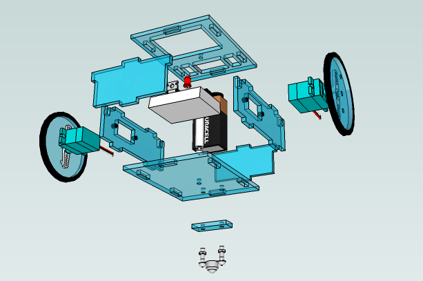
Here’s an expanded view of mini grisbot. I tried to learn from previous experience and incorporate design changes accordingly. Indeed, this design is probably going to change as well.

Just so we’re clear, minigris is a very small robot:

minigris scale

Posted in Uncategorized | Tagged , , , , | Leave a comment