More surgery on a servo

DSCN9140

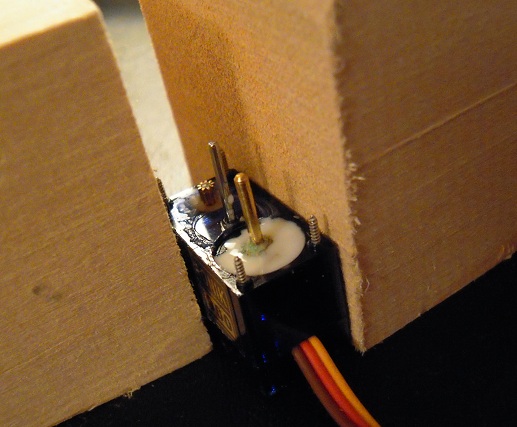
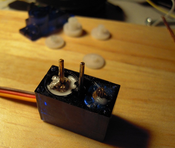
No, it didn’t crash. I had to disassemble mini grisbot in order to perform surgery on the right servo, whose centering had drifted so much that the wheel could not turn forward.

To keep the potentiometer shaft from twisting (thereby drifting) again, I fill the potentiometer well with glue. Online instructions for servo conversion recommend hot glue for fixing the position of the pot shaft, but surface tension causes the glue to bead and that interferes with the turning of the bottom gear. By applying cold glue with a toothpick, I can spread the glue flat.

This is what I did on the other servo, and I haven’t had any problems with that one . . . yet.

DSCN9141

Posted in Uncategorized | Tagged , , | Leave a comment

Mini Grisbot in action

Preliminary test of my robot.

Posted in Uncategorized | Tagged , , , , | Leave a comment

Mini grisbot test status

DSCN9019a

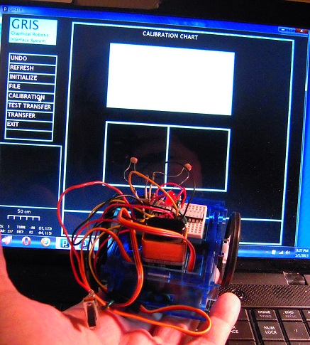
I have completed screen-to-photocell calibration and control code transfer. Mini grisbot passes both with flying (or at least hopping and skipping) colors. The remaining test phase is to calibrate the servo timings to execute the path as shown on the screen.

I just might finish this today.

Posted in Uncategorized | Tagged , , , | Leave a comment

2013: Year of the Raspberry Robot

raspberry robotics

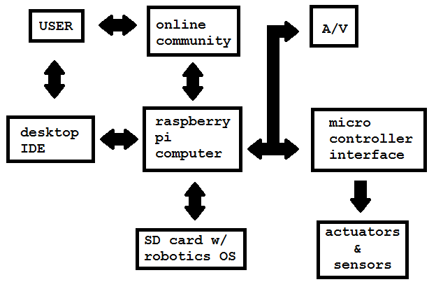
My interest in the Raspberry Pi concerns its use as robot brains. I made the above chart to help me better understand where the Raspberry Robotics development process is heading.

I’ll need an IDE on my laptop/desktop which can transfer files from the online community and my computer(s) to the Raspberry Pi without the need of having to find a spare monitor and keyboard for the Pi. A pre-loaded SD card with a robotics-oriented operation system would make configuration a lot easier.

The Arduino/ATMega could serve as an interface between the Pi and the sensors and actuators, taking advantage of the great pre-existing library of interface ‘sketches’ that already exist for the Arduino. Audio/Visual will connect directly with the Pi, and the IDE will need to pipe in the vision and sound for development and troubleshooting.

From what I’ve read about it so far, the Raspberry Pi is destined for great things robot-wise. It appears to have enough onboard processing power to perform visual pattern recognition and object manipulation, which could mean that soon we’ll be seeing Raspberry Robots setting the table, taking out the garbage, shoveling the snow, performing brain surgery, and driving trucks. Well, maybe not driving trucks.

Even the simplest tasks will require lines and lines of programming, requiring a vibrant online community for me to copy and paste stuff from.

Happy New Year, which for me will looks like it will be the Year of the Raspberry Robot.
Posted in Uncategorized | Tagged , , , | Leave a comment

Robot Sentry Duty

Obviously, there’s going to be course error buildup. I don’t think encoders would help that much. I’m thinking of navigation beacons, like so:

beacon

(Maybe infrared? Hmm . . . . )

Posted in Uncategorized | Tagged , , , | Leave a comment

Naked ATMega circuit layout

naked-atmega3

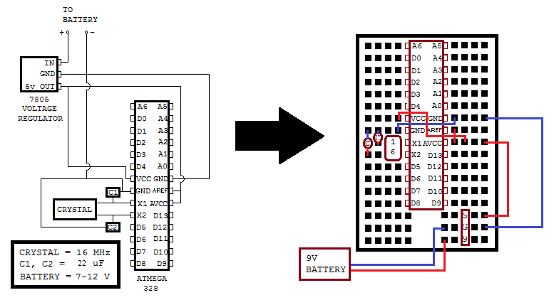
This is related to the previous entry and shows the circuit diagram and breadboard layout for an ATMega removed from the Arduino prototyping platform after being programmed. The wiring layout on the right isn’t mandatory, of course, but it does conserve on the voltage regulator’s 5V and Ground row holes.

(Jan 15, 2013 REVISION: Changed capacitors from 10 uF to 22 uF.)

Posted in Uncategorized | Leave a comment

The Naked ATMega

Why take the ATMega328 chip off its happy home on the Arduino to sit naked on a breadboard? Because Arduinos cost $22 while the ATMega328 with Arduino bootloader runs about $1-2 plus a dollar for the support components and a couple dollars for the breadboard. So if you’re planning on making a lot of microcontroller projects and don’t need to connect to wi-fi or USB and stuff, the ‘Naked ATMega’ is the way to go in order to stay within budget.

Permit me to show you how incredibly easy it is to move the ATMega chip off the Arduino prototyping platform once you’ve programmed it, and then bring it back to the Arduino board for reprogramming as needed:

This slideshow requires JavaScript.

NOTES.

0. The breadboard layout for an ATMega328 with support components and wiring is derived from the Mintduino Instructable. I skipped some resistors and capacitors on the voltage regulator, but it seems to work.

1. Take it slow and easy, be gentle. As mentioned in a previous entry, I crimped pin D9 by not being careful.

2. Probably should have unplugged the Arduino from the computer before removing the chip.

3. I don’t know what the yellow handled tool is called. Let’s go with ‘prying tool.’

4. The device used to push the chip into the breadboard is known as a ‘pen.’ (No overthinking here, folks!)

5. A pin identification sticker for the ATMega is very helpful. Here are some.

Posted in Uncategorized | Tagged , , | Leave a comment

Surgery on a servo

DSCN8784

Servo drift occurs when the potentiometer shaft (the one on the left in the photo) turns from the centered position (ie 90 degrees). I tried to prevent servo drift by soldering the pot shaft in place, but apparently all I did was solder it to a piece of metal that rides on the shaft above the pot body. Hence: drifting.

Resoldering didn’t work, so I tried glue this time. It’s cold glue, though, and servo conversion procedures recommend hot glue. Hot glue is a hassle, though. I want to see if cold glue works.

(Photo notes: the glue is the white stuff at the base of the potentiometer shaft. The previous solder is the silvery stuff on top of the metal plate, after efforts to de-solder. The solder which somehow ended up on the shaft easily snapped off. On the right, the grayish goop on the motor gear is a lubricant put there by the factory.)

Posted in Uncategorized | Tagged , , , | Leave a comment

Servo Center Location Test

DSCN8752

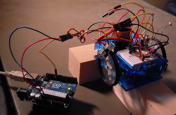
It looks like the climactic scene in a monster movie, Arduino vs. Bot. In reality, this setup enables me to keep the ATMega328 chip on the Arduino while I upload test programs to locate the servo centers.

According to the results, the left servo center has drifted from 90 to 99 degrees while the right center is at 65! Maybe during conversion from fixed to continuous, I should have hot glued the potentiometers instead of soldered.

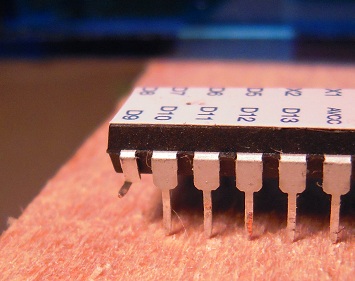
BTW, here we see the tragic story of pin D9, a casualty of moving the ATMega back and forth between Arduino and Bot without enough care:

DSCN8751

Despite the mangled leg, the rest of the microelectronic centipede is limping along just fine, so there’s no reason to replace it just yet. And so the battle goes on . . . .

Posted in Uncategorized | Tagged , , , , , | Leave a comment

Minigris test matrix demo

This demo shows that the mini grisbot (graphical robotic information system) test matrix has been successfully completed, with photocells and servos functioning and integrated.

(And special thanks to Adafruit for the link yesterday.)

Posted in Uncategorized | Tagged , , , , | Leave a comment