
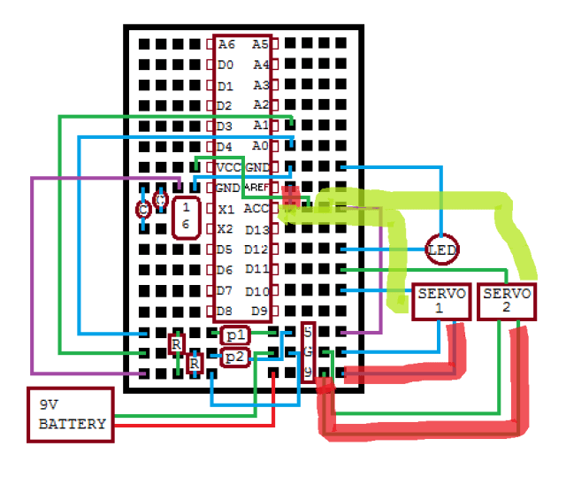
Well, I did notice that the servos were going to nine volts rather than five on yesterday’s schematic, so I fixed that. Also deleted the connection to AREF per this. But I couldn’t even get the LED to light up when I did a test of the fully assembled system. My presentation at SRS on Saturday morning was a ‘static demo,’ alas.
And in case you’re wondering, yes, I did check the battery and voltage regulator. Tomorrow I’m going to take the circuit apart completely and then build it up from the bare ATMega328 chip and support components (voltage regulator, crystal, caps, etc.). I’ll see if I can get that LED to blink, then integrate the photocells and servos. The components have worked separately in the past, and I’m confident that they can work together too.

Actually, the connection between AREF and ACC (ie AVCC) needs to be there. I mistakenly omitted it because I was referencing a circuit design that uses a Lillypad bootloader, whereas I’m using a regular Uno bootloader. I would prefer to use the Lillypad bootloader because then I wouldn’t need the external crystal and capacitors, but I would have to get an AVR programmer in order to burn it onto the chip. Another day, perhaps.