
I drew up some alternative designs for the casing, like so:
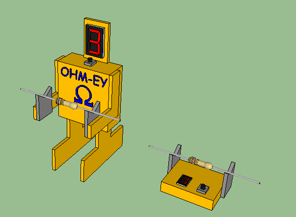
The design on the left is a laser-cut version of the robot case. The box design on the right is the utilitarian model, of course.
Now for the pushbutton circuit and the auto-off function:
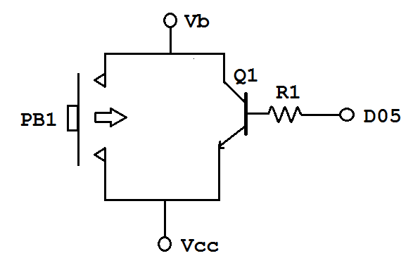
When the user presses push button PB1, it allows battery power Vb to pass down to Vcc, which inputs voltage to the microcontroller and powers the microcontroller. When the microcontroller powers on, it notes the time (= tstart) and sets pin D5 in digital output mode to HIGH. This turns on transistor Q1, providing a circuit path from Vcc to Vb so that the microcontroller continues to be powered after the user releases the push button.
The microcontroller program then performs the ohmmeter measurement and display functions as described in the previous entry. While the functions are executing, the microcontroller also checks the time and compares it to the initial time tstart. When the present time is, say, thirty seconds past tstart, the program sets pin D5 to LOW, which causes transistor Q1 to turn off, which causes the circuit between Vb and Vcc to break, which causes the ohmmeter to turn off automatically.
An improvement on this might be to have the ohmmeter also turn off automatically after it has displayed the reading three times.
Another improvement would be to figure out how to activate the circuit without the need for a pushbutton.
