Autofade Table Lamp

Years ago, my car had an interior light that would come on when the door was opened, then slowly fade away when the door was closed. I now need something like that for my apartment.

The light switch next to the front door of my apartment is inoperative, but that’s not the problem. Even if I were to put a lamp next to the door, I would be turning it on when I enter, walking to the light switch at the other end of the room to turn that on, and then have to walk back to the door to turn that light off, and then walk back to the other end of the room where I spend most of my time.

So how do I avoid that extra trip back to the door? That’s where the autofade table lamp concept comes in.

I want a portable lamp that I can turn on with a touch, and it will stay lit for about thirty seconds, long enough for me to cross the otherwise darkened room and turn on the light at the other end. Then the autofade lamp will shut itself off, sparing me the need to walk back and turn it off.

Here’s my first crack at a physical design:

You press down on the top, which in turn presses a button inside the box. The button closes a circuit that causes the light to come on. The light is next to the button, but you really can’t see it in this picture, so let me remove the top:

All right, and you can also see the battery compartment lid as well.

The problem with this design, I realized after staring at it for a while, is that the light is going to be shining in my eyes. So I realized, why not put the light lower, and have it shine through the sides. So I redesigned it that way, and made it a trifle more decorative.

And here’s a close-up:

The white plastic top would be hollow with thin faces, so that a soft glow would come through it when the light was on. Not enough to be blinding though.

Well, enough exterior design. What about the schematic? I had hoped it would be a simple matter of putting a capacitor in the circuit, but even big capacitors retain only enough charge to keep even a small light lit for barely a second or so.

So then I thought, why not have a capacitor drive a transistor, which drives the light? That gave me this schematic:

Pressing the push button charges the capacitor and turns on the transistor, which causes the light (an LED here) to turn on. When the button is released, the capacitor continues to supply current to the transistor, which then keeps the light on for a while longer.

Well, there are a couple problems. First, the user has to keep the button pressed until the capacitor is fully charged. How long does that take? I don’t know. Based on a breadboard test I did, though, I don’t think it would take more than a second or two.

The bigger problem is that the transistor might require a minimum amount of base current in order to allow any collector current at all, and that current could be pretty much the same as what an LED drinks. So despite a huge current gain, maybe I haven’t reduced my current requirements. Being a digital guy, I don’t have much experience with transistors in analog state (or is it mode?), so I can’t say.

Well, another thought is just to forgo electronics entirely, and just use something sticky to keep the top pressing down on the button. Eventually the spring pressure of the button overcomes the stickiness, and the top is pushed back up again, and with the button no longer being pressed, the light goes off.

Perhaps maple syrup could be used. The problem then is to keep the syrup from overflowing the sides of the . . . well, I probably won’t use syrup. I think I’ll see how things go with electronics first.

(BTW, I want to have the capacitor drained of residual charge once the transistor turns off. That’s what resistor R3 is for. It has a much bigger resistance than the other resistors or the internal resistance of the transistor, of course, so that it has little effect on how long the capacitor charges or how long the light is on. But it does make sure that the capacitor will fully drain even if something happens to the transistor.)

Anyhow, time for a test circuit.

Posted in Uncategorized | Tagged , , , , | Leave a comment

In Defense of Steve Jobs

10 Unusual Things I Didn’t Know About Steve Jobs

Why do I get the feeling that this alleged ‘tribute’ is actually a hit piece in disguise?

Steve Jobs is dying and is rumored to have only weeks to live, and so the writer takes the opportunity to inform us of every bad thing Jobs did as a teenager.

“I make no judgment,” the writer says. Well, I’m not actually accusing the writer of character assassination in a commissioned hit piece in a public relations smear campaign for a corporate power struggle to purge Jobs supporters at Apple after Jobs is gone.

Instead of judgment, let me offer perspective.

Not as a teenager nor as an adult has Steve Jobs ever foreclosed on a single mother or swindled a widow out of her pension or gone to the government to demand a bailout for a ‘business’ that does nothing but speculate with money printed out of nothing at the expense of working people and the poor.

Instead, with his leadership, his companies create products that make the world a better place, and for all the airing of petty grievances, every person who has had dealings with him has become insanely rich as a result.

And so when it comes to Steve Jobs, make your own judgment.

Posted in Uncategorized | Tagged , , | Leave a comment

High Moon

Way back when, I wrote a science fiction novelette called “High Moon,” about teleoperated lunar mining robots in Wild Old West Cosplay. It appeared in the May 2005 issue of Analog Science Fiction and Fact Magazine, the longest-running print magazine in the science fiction genre.

Well, I have published it online at FictionPress.com. Be sure to adjust the font and width settings to your liking. And with that said, the link is here.

Posted in Uncategorized | Tagged , , , , , , , | Leave a comment

The Mystery of the Backwards Transistors

I’ve made a video correction to my video about a PC to arduino to toy crane interface. The second video is called The Mystery of the Backwards Transistors.

Anyhow, if you missed it, here is the first video:

And here is the correction:

Posted in Uncategorized | Leave a comment

Transistor Follies

My electrical engineering education at the University of Washington back in the late 1970s was long on theory and short on hands on experience. Hence it wasn’t until recently, when I started to fool around with electronics, that I needed to know which way on a transistor was up.

Yeah, pathetic, I know. Especially since while I spent much of my college years almost in tears, grinding out partial differential equations to perform circuit analysis that is now performed instantly by inexpensive PC software, a bunch of geeks who never went to college jump-started the personal computer revolution thanks to their hands-on experience as electronics technicians. There’s a lesson there somewhere. Too bad I don’t have a life to live over again.

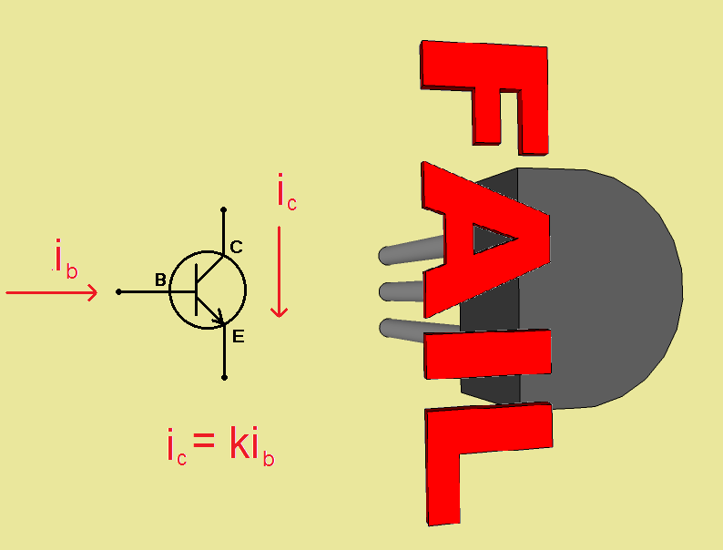
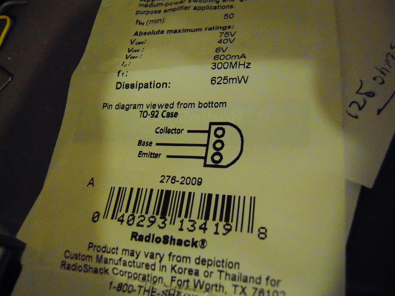
So, uh, which way on a transistor is up? I made the mistake of seeking the answer on the internet, and so I was doomed. Lo, the truth is on the back of any package of transistors:

So you’re wondering, “Why didn’t you just look at the back of the package instead of online?” Well, my first transistor was cannibalized from a Certain Microcontroller Kit (not an Arduino) and the transistor came in a clear plastic package with no information whatsoever. So I looked up the pin configuration on the internet. And from then on, I assumed that the incorrect information was correct, so I didn’t bother to look at the back of the information-rich packages when I did buy more transistors.

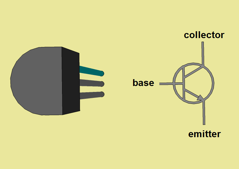
Just so we’re clear, I’ve hi-lited the collector pin in the following sketchup drawing. The hi-lite color is cyan, because ‘c’ is for ‘collector’ and ‘cyan.’

Now, since I no longer trust my aging brain to rotate drawings in three dimensions, I’ll let Sketchup do it for me, and then I’ll provide a transistor symbol for illustration.

This is how it should appear when you’re looking at it on a breadboard. The memory trick I’m going to use from now on to remember this is that when the transistor case is oriented so that it resembles a ‘C,’ the collector pin is on top.

All right, that’s settled. But after realizing the error of my ways, I started to wonder, “If the transistors were installed backwards, how come the circuits I’ve designed have still worked?”

Well, according to a technical forum on the internet (technical forums being about the only place on the internet where reliable information is to be found), transistors work even if they’re installed backwards!

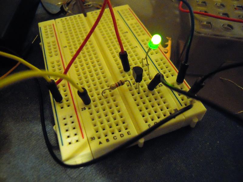
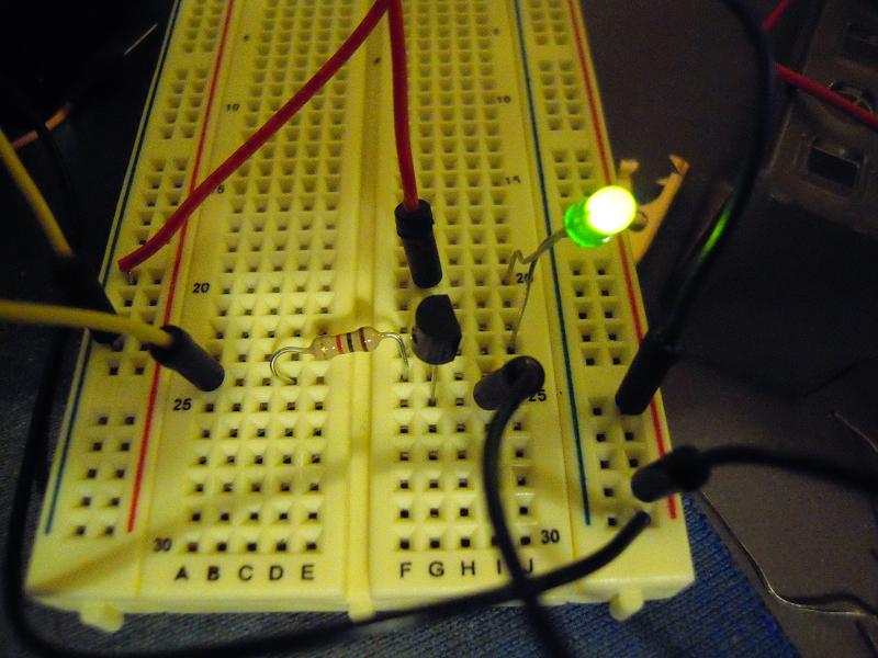
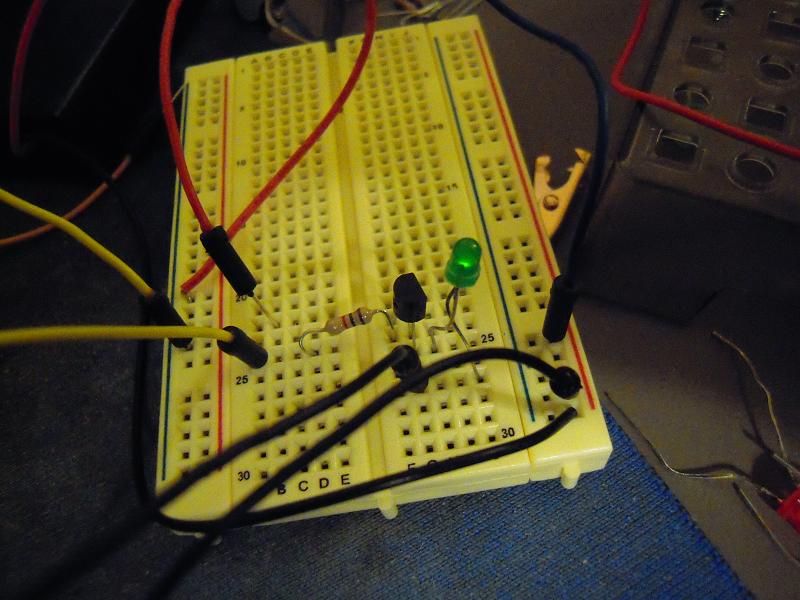
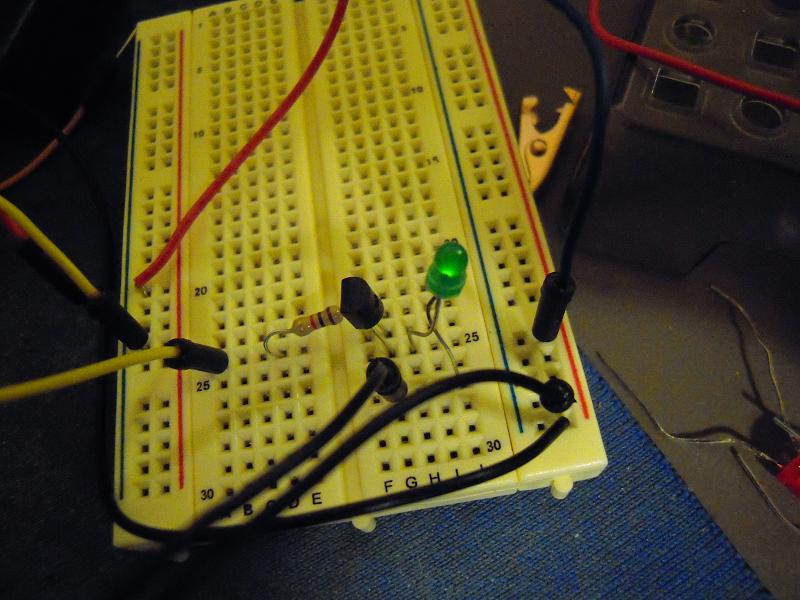
“Nah,” I said. But it’s true. So I made a little test circuit which allows current to pass through an LED and transistor (see photos below). The LED lights to show that the transistor is ON.

We’ll call this the ‘D’ (for Dumb) configuration:

And you’ll notice, that’s how it looks in my crane video (which I’m going to update, BTW). And you’ll also notice, the LED is a-shining!

Well, just for grins, here’s the ‘C’ (for Correct) configuration:

So yes, Virginia, transistors do in fact work when they are correctly installed.

In fact, they even kinda work when they are only half installed, as shown here when the collector is disconnected:

And just so we’re sure on this, they even sorta kinda work when the collector is disconnected and they’re installed backwards:

You know, for all the bad-mouthing hardware gets, it’s more forgiving than software. You forget a parenthesis while writing a Processing sketch, and the IDE lets you know about it. But maybe such nitpicking is a good thing.

You see, there is a price to be paid for installing one’s transistors backwards. It turns out that the current gain (ie, the ratio of collector current to base current) is much less. I will now have to wonder if maybe the Arduino-to-crane interface would have worked with 1K resistors if I’d had the transistors installed correctly.

Something to think about while I update the video.

Posted in Uncategorized | Tagged , , | 2 Comments

PC to arduino to toy crane

Posted in Uncategorized | Tagged , , , , | 5 Comments

St. Helens quakes move under the caldera

The Daily News Online, which serves the lower Columbia River region in the south of Washington State, reports on the recent St. Helens volcano earthquake swarm of this past week, and concludes:

The quakes are occurring along a fault known as the Mount St. Helens Seismic Zone, which stretches from an area immediately northwest of the mountain and into Lewis County. Seismologists continue to say the quakes are caused by relief of stresses in the earth’s crust and are not a signal that the volcano is getting ready for another eruption.

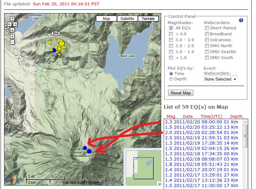
Well, in the past twenty-four hours, there have been two quakes of magnitude 2.0 or greater which have occured directly beneath the dormant volcano’s caldera. This is shown at the Pacific Northwest Seismic Network page:

Notice that the depths for the caldera quakes are only slightly more than a kilometer. The depths of the St. Helens quakes have been getting closer to the surface by about a kilometer a day.

Even if magma reaches the surface, it may not be such a big deal. In 2006, there was a 3.1 quake that resulted in a plume of ash and smoke that frankly I had forgotten about, and I doubt many people in the state recall it either. If you’re interested, read about that here.

Anyhow, we might be seeing another plume early this week, and I hope it’s of only scientific interest.

Posted in Uncategorized | Tagged , , , , , , | Leave a comment

Electronic Schematics in Sketchup

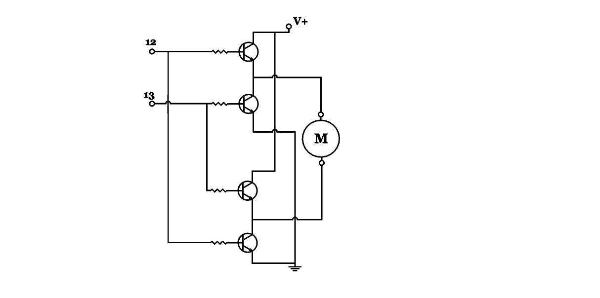
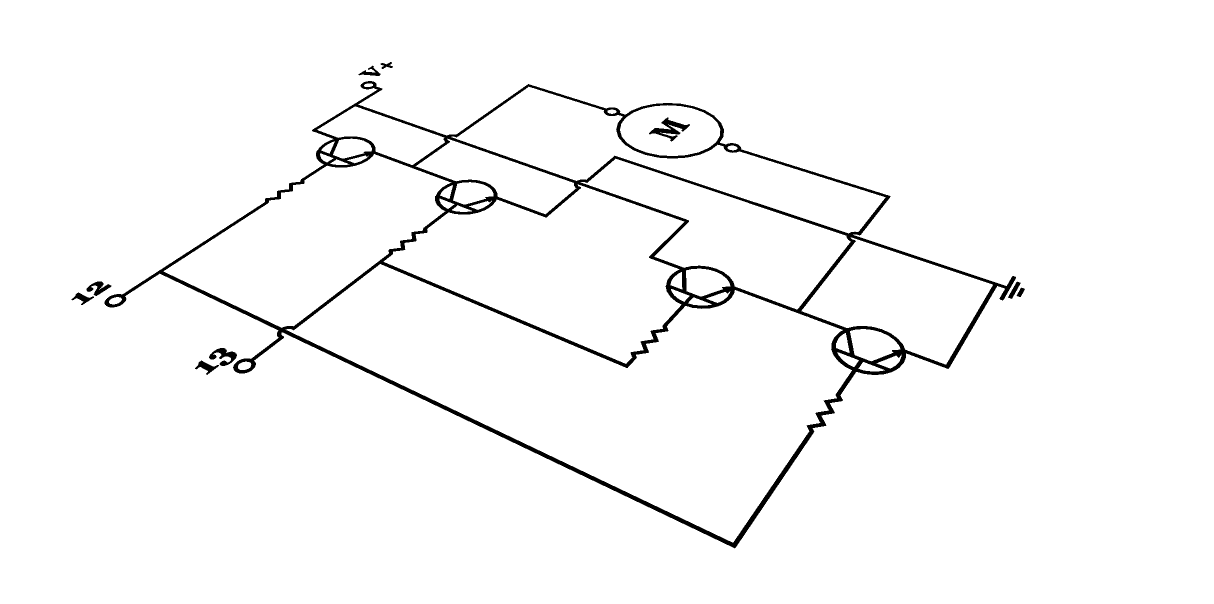
Sure, your electronics graphics program can make 2D schematics. But can you do this?

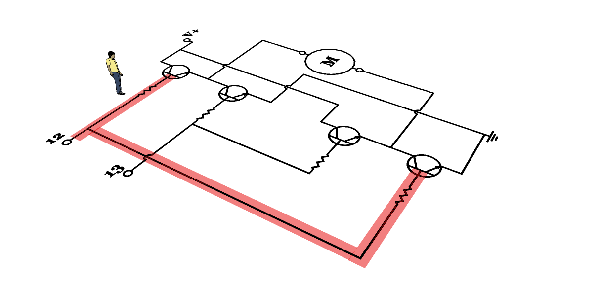
“Why would I ever want to do that?” you ask. Well, say that you’re putting together a presentation and want to hi-lite specific parts of the circuit, like so:

Sang is now calling attention to a specific resistor and the red transparent line is showing what happens when pin 12 goes high. The angle of viewing calls attention to the input side of the circuit.

Well, I think it makes a circuit schematic look visually appealing as opposed to Zzzzzzzzzzz. But maybe that’s just me.

As for what this circuit does, well, I’m working on a presentation.

Posted in Uncategorized | Tagged , , , , , | Leave a comment

Mount Saint Helens Seismic Data Visualization

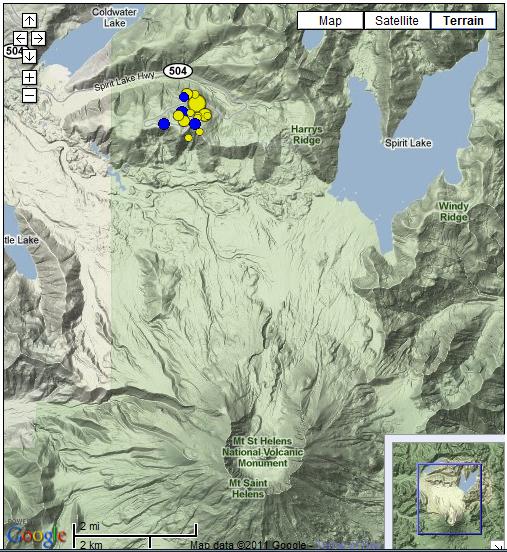
This is an attempt to visualize data from recent seismic activity around Mt. Saint Helens. Nothing fancy, I simply used Google Sketchup and imported the quake map off the Pacific Northwest Seismic Network page for around 2PM Thursday Feb 17, 2011, then made cylinders proportional to the depths (which are given on the PNSN page). Yellow means in past two weeks, blue in past two days, red in past two hours.

And what have we learned? Hmm, good question. Well, it does kind of look like whatever is under there is moving swiftly west and upward.

Posted in Uncategorized | Tagged , , , , , , , , | Leave a comment

The Volcano Beside Me

As a native of the Seattle region, I have often found it disconcerting to hear about killer weather, of tornadoes, hurricanes, cold snaps, and heat waves that leave death tolls in their wake. All we have to complain about around here is the rain, which usually is just a drizzle, so maybe we should feel blessed.

But then we have a volcano. In 1980, Mount Saint Helens erupted, spewing billions of tons of ash mainly over the eastern portion of the state. Well, maybe it’s not that big a deal, for although Seattle is only about a hundred miles north, we weren’t inconvenienced — except to stock up on disposable paper dust masks in the event of a dump of volcanic dust.

But then my grandfather wasn’t so fortunate. His town of Yakima was buried under inches of ash. He climbed onto the roof to sweep it off with nothing more than a wet handkerchief for a dust filter. The dust, the exertion, his age (76), and a lifetime of smoking combined to cause a fatal heart attack.

So it is with personal concern that I read that on Valentine’s Day, the area around Mount Saint Helens had its strongest earthquake in thirty years.

Here are a couple screen captures from the Pacific Northwest Seismic Network page. The first shows the geographical location of the volcano relative to Seattle:

The second is enough of a close-up to separate the event dots:

There are a lot of event dots. Yellow means in the past two weeks, blue in the past two days. When I got up this morning, there was a red dot, which meant a quake had occurred in the past two hours.

For perspective: the quake that occured on Valentine’s Day was magnitude 4.3, equal to an explosion of 2000 tons of TNT, enough to blow up a small city had it occurred on the surface rather than 5.5 kilometers underground.

This morning’s quake of 2.4 is equal to only about a couple tons of TNT, but then the depth has risen to four kilometers.

In the news this week has been Yellowstone Park, the site of a supervolcano which in past cyclical eruptions has wiped out 90% of life on Earth. And as seismologists like to say, “It’s due.” Here’s the Youtube video of the CNN report.

In contrast, I’m surprised at how little coverage there has been about Mount Saint Helens. Yellowstone erupted 600,000+ years ago, so statistically the odds that it will erupt this year are low. But Mount Saint Helens had a major eruption only three decades ago, and the odds that it will erupt this year appear to be high enough for concern rather than just speculation. In my ignorance about seismology, I can wonder if the increasing pressure under Yellowstone could vent itself laterally via Mount Saint Helens.

The Seattle Times article about the Valentine’s Day Saint Helens earthquake doesn’t mention that it was the biggest in thirty years, and the comments are quite complacent and even cavalier. Young people. For me, though, it’s been thirty years since I thought local volcanic eruptions were cool.

If there is another major eruption, the winds may blow differently this time, but I guess there’s not much I can do other than put dust masks on my shopping list.

Posted in Uncategorized | Tagged , , , , , , , , , | Leave a comment