Can robots stop a meltdown?

Forbes Magazine, “Risk of Nuclear Catastrophe Escalates in Japan – ‘Worse than Chernobyl'”:

“The electrical grid is down. The emergency diesel generators have been damaged. The multi-reactor Fukushima atomic power plant is now relying on battery power, which will only last around eight hours. The danger is, the very thermally hot reactor cores at the plant must be continuously cooled for 24 to 48 hours. Without any electricity, the pumps won’t be able to pump water through the hot reactor cores to cool them. Once electricity is lost, the irradiated nuclear fuel could begin to melt down. If the containment systems fail, a catastrophic radioactivity release to the environment could occur.”

Being a proponent of teleoperated robots, my response was to think of how teleoperated robots could help in environments such as fire and high radioactivity where humans cannot function.

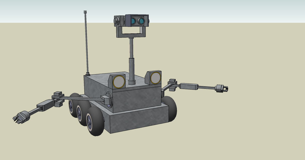
So I stripped down my sketchup design for a teleoperated robot:

Robots like this could drive portable generator trailers to the reactor plant site. They could connect the generators to the reactor power system. They could get the cooling pumps running and operate them.

Japan must have a thousand university robotics students who could assemble a team of such robots in a matter of hours from the spare parts of class projects.

The Japanese are smart. So either they’re doing this, or something more effective, and we’re just not getting the full details in the US media.

It bothers me that the US response to this crisis is to send an aircraft carrier. We sent one to Haiti after their earthquake, and they still haven’t recovered. It’s an American compulsion these days to think of every problem in terms of military solutions.

However, I am confident that Japan’s leaders do think about engineering as a way to solve problems, and so Japan will survive this crisis.

Posted in Uncategorized | Tagged , , , , | Leave a comment

Just to replace a laptop screen cable

So my nephew’s T*sh*b* laptop screen was blinking when he tilted it, and now it doesn’t work at all. Most likely reasons, according to internet forum gurus, are the screen cable or the inverter. Okay, we’ll just open up the screen enclosure and replace the faulty parts. Easy peasy.

Not so fast.

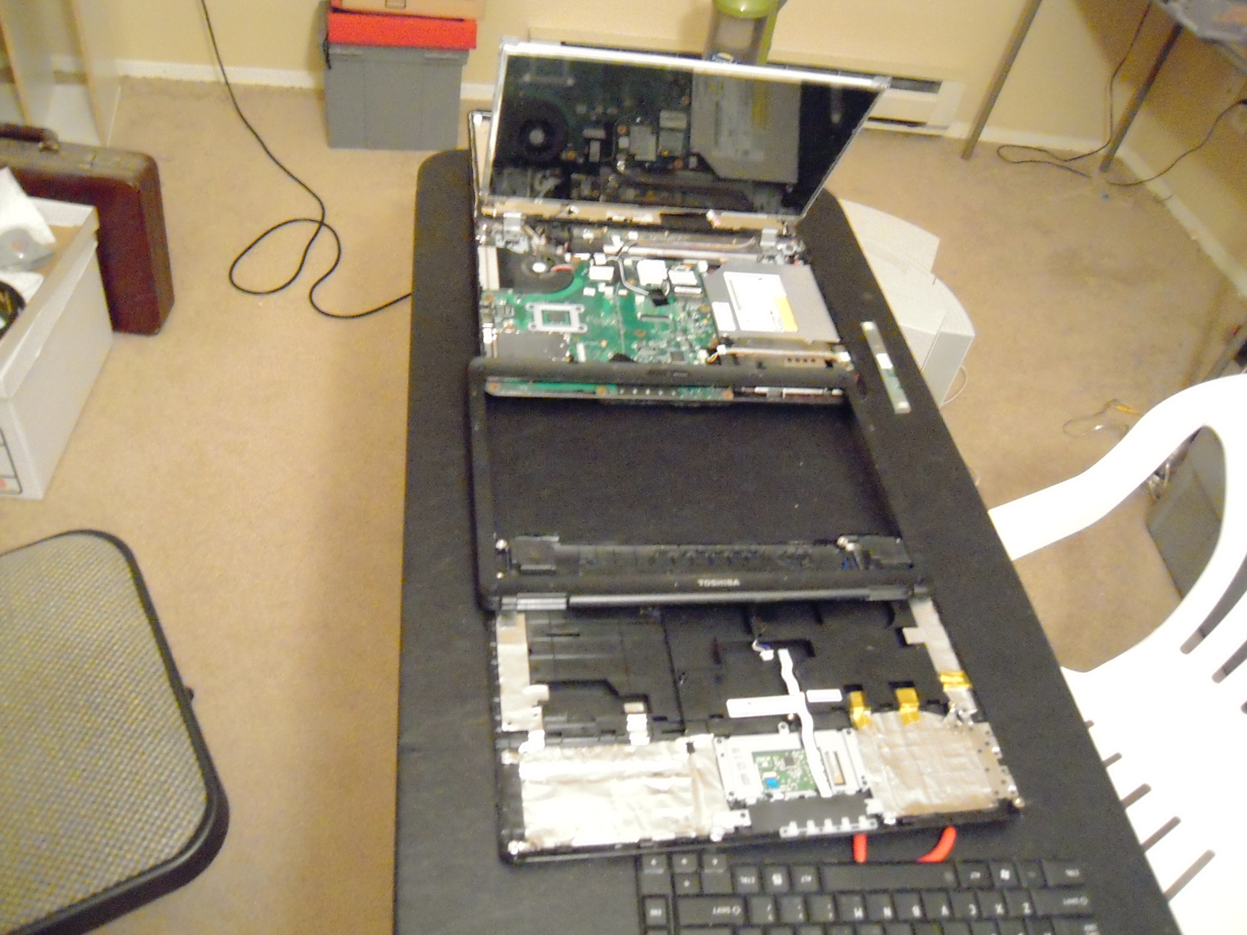
First you have to remove the battery. Then some screws. A lot of screws.

Then you can pry off (good luck with this) a plastic strip at the top edge of the keyboard. Then you can remove the keyboard.

At this point, you’re wondering, “Weren’t you trying to get to something having to do with the screen?” Well, we’re getting there.

Now you pry off the cover (which doesn’t really doesn’t want to go). Now you can remove the bezel. That’s the plastic rim around the screen, which you would have guessed would have come off on its own, without having to remove the cover of the body of the computer first. But you would have guessed wrong.

Okay, that there’s the inverter. It came from just under the screen. We may have to replace it. It’ll cost $35.

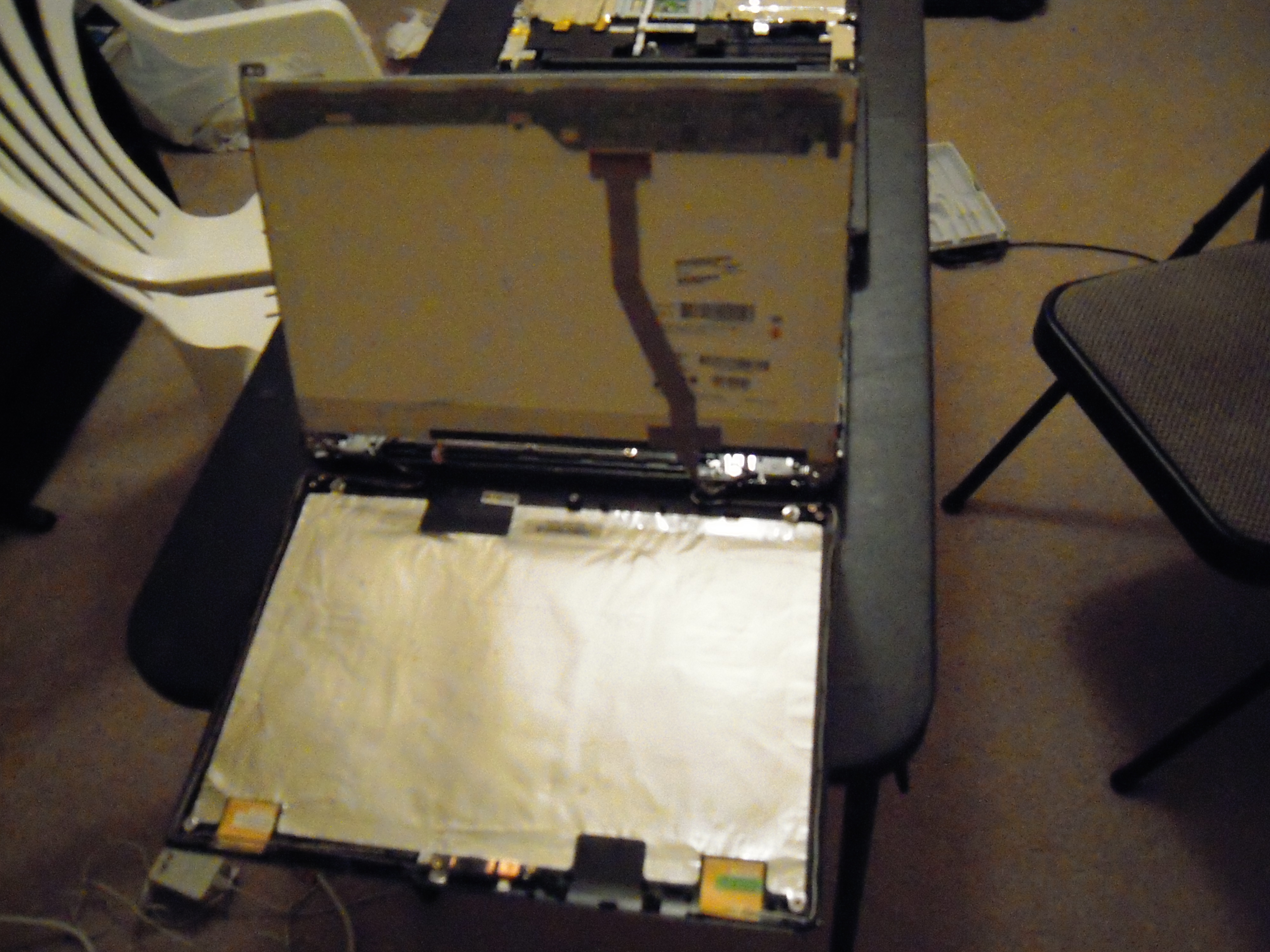
Now, on the other side of the screen, we see the cable that connects the electronics on the top of the screen to the computer body. Wouldn’t the cable be a lot shorter if the screen electronics were at the bottom rather than the top? So why was the screen installed so that its circuit board was at the top, requiring a longer cable to connect to the body? Perhaps there might have been electromagnetic interference problems.

EMI might also explain why the back of the screen enclosure is covered with foil. But I’m only guessing, and I’ve been known to guess wrong.

All right, here’s where the screen cable goes into the computer body. Notice there are a couple points where it could have been crimped and damaged through just normal wear and tear. This confirms my suspicion that the cable is the problem.

BTW, if I had been designing this thing, first of all I would have made it possible to access the screen inverter and cable simply by unscrewing the bezel. And then I would have sheathed the critical cable points with ABS plastic tubing to protect the cable from crimp damage.

I hope the cable costs less than $35 to replace. I figure we’ll price it tomorrow and order a replacement, then do something else while the part is on its way.

To tell you the truth, I look at this mess and wonder if the laptop will ever be the same again. I told my nephew that we may just put it in a box and attach an external keyboard and monitor, and ta-da, a new desktop.

That’ll be Plan B.

Posted in Uncategorized | Tagged , , , , , , | Leave a comment

Pricing a Mining Robot: Communications

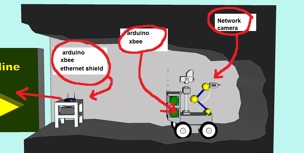
So I want to build a teleoperated mining robot to operate over the internet. I provided a graphical overview of the system here. Today my nephew and I priced the communications-link components.

Supposing for the moment that I actually know what I’m talking about, here’s what I figure we need:

Let’s start from left and go right. First, at the entrance to the cave, you have a router that connects to the internet. That’s fifty bucks.

The router connects to an ethernet shield. The ethernet shield enables the router to communicate with an Arduino.

The Arduino in turn connects to an Xbee, which is an Arduino shield that enables the Arduino to send and receive point-to-point radio communications.

On the robot itself is another Xbee shield, which receives and transmits radio signals on behalf of an onboard Arduino. The onboard Arduino in turn interfaces with the wheel motor(s) and manipulators and other systems and sensors of the mining bot.

Altogether you need 1 ethernet shield ($55), 2 Arduinos ($70), and 2 Xbees ($50), for a total cost of $175. Oh, and I forgot that router, didn’t I? Well, that’s $225 then. Tax and shipping and handling not included. (Groan.)

Then there’s the camera, but that turned out to be the easiest and cheapest of all my communications problems. I checked Amazon and found a home security camera that connects over the internet for just $70. I would mention the brand and provide a link, but hey, I’m not getting paid for product endorsements here.

Anyhow, I bought the camera and it’s coming via Super Saver shipping, so it’ll be here next week or so.

In the meantime, it’s back to the neph’s computer. You know, I’m going to have to buy a marker board to keep track of all these projects.

Posted in Uncategorized | Tagged , , , , , , , , | Leave a comment

Laptop of Doom

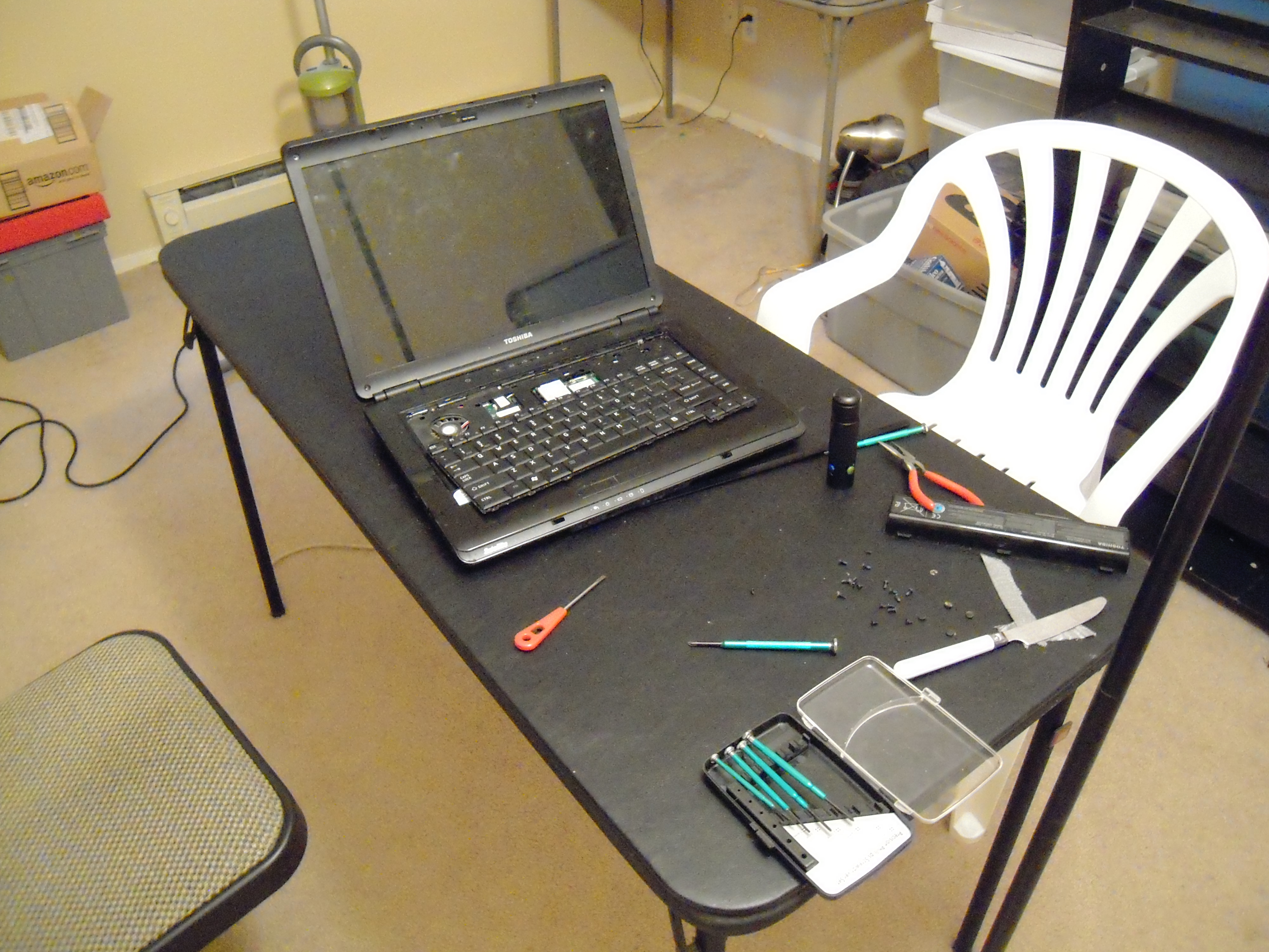
My nephew dropped his Toshiba laptop X number of times, X being a number larger than the number of times that you should drop a laptop. Anyhow, the screen started flickering whenever he tilted it, and then it blacked out entirely. It’s been that way for a while now, and I put off repairing it until I could get the back room cleaned out so that we would have a place to work, like so:
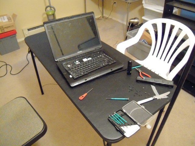
After consulting technical forums, I had determined that the problem had something to do with either (1) the cable connecting the main body of the computer to the monitor, or (2) the screen inverter.

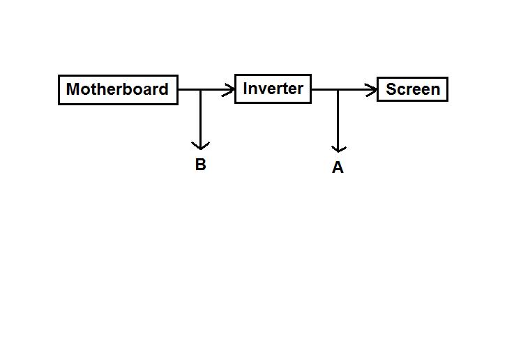
Now, the laptop has a connection for an external monitor, and I had the impression (mistaken, it turns out) that the inverter was ‘upstream’ of where an external monitor connected. See ‘A’ in this diagram:
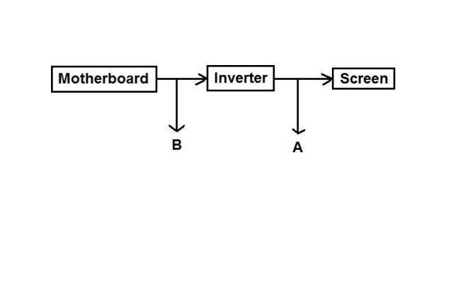
This gave me the idea (again mistaken) that if I connected an external monitor, I could determine whether the problem was the cable or the inverter, because if the external monitor showed anything, then the inverter had to be okay. Again, this was assuming that the external monitor connects after the signal comes out of the inverter. (Please don’t hit me for thinking that. I know better now, but let’s go on.)

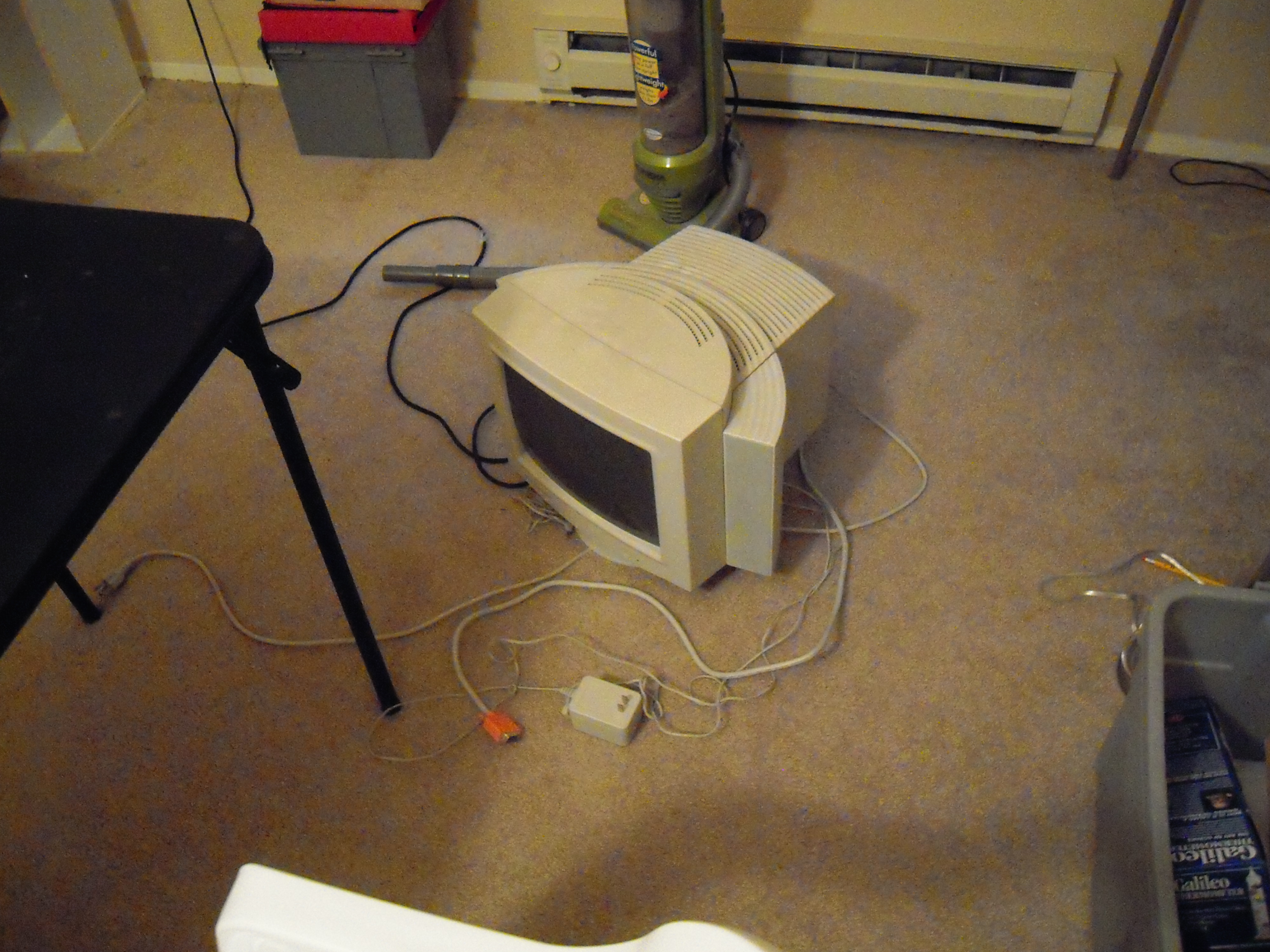
And so it came to pass that I took an old desktop computer monitor from the 1990s and connected it to the laptop’s auxiliary screen port. Here’s what the old monitor looks like:

Notice the bulky speakers with the tangle of cables connected to the sides of the monitor. This is what passed for ‘computer design innovation’ in the 90s.

The result was that the screen image came up on the old monitor, so I concluded (mistakenly — do I have to keep saying that? Yes, I do. It’s my penance.) that the inverter was okay.

After some tinkering, we got the password screen. My nephew typed in his password, and we got the welcome screen. But that’s as far as we got. Now he tells me, “I think my computer may have been zombified.”

Well, that’s something else to think about.

Anyhow, it seemed that the next thing to do was see if the cable was loose, and to do that, I had to unscrew the case. My impression of Toshiba laptop repair is that there are a lot of screws to unscrew. And finally I realized that the top wouldn’t come off even though I had unscrewed everything in sight. So to the Internet, Robin!

I went to irisvista.com and the step-by-step illustrated instructions patiently explained that in order to remove the screen, I first had to remove the keyboard. Why of course!

We finally got the keyboard off, but by then we had run out of time for today. So we’ll go further tomorrow, but I’m not sure how further.

Now, as I mentioned earlier, I had thought that if we got something, anything, on the external monitor, then the problem wouldn’t be the inverter. Then I got the uneasy feeling of self-doubt I always belatedly get when I declare something with great self-assurance, and so I did an internet search to a site called Laptop Parts 101, and from the picture it appears that the external monitor is ‘upstream’ from the inverter. Translation: the external monitor actually taps off at point B in the diagram I showed earlier, and connecting an external monitor doesn’t really tell me if it’s the inverter or the cable that’s at fault.

Well, anyhow, I think we can replace the inverter easiliy enough. But that will cost $35. (Hmm, that’s beginning to be a familiar price point . . . . )

And then what about the ‘zombification’ issue? Well, maybe it’s time to load Linux. My nephew doesn’t like Linux, but I don’t think we have the boot disks for Vista anymore and we’ve got to do what we’ve got to do.

I coming to think that what we’ll end up doing is burying the poor thing and buying a new computer. This time it’ll be a desktop, because I want to upgrade the graphics card. Also, it’s harder to drop a desktop, though to be fair he is seventeen now and seems to be out of the klutzy phase of adolescence.

(Now, if only I could get out of the klutzy phase of middle age . . . . )

Posted in Uncategorized | Leave a comment

Autofade with Fritzing (A review)

From Fritzing.org:

Fritzing is essentially an Electronic Design Automation software with a low entry barrier, suited for the needs of designers and artists. It uses the metaphor of the breadboard, so that it is easy to transfer your hardware sketch to the software. From there it is possible to create PCB layouts for turning it into a robust PCB yourself or by help of a manufacturer.

To give you an idea of what it does, here’s a breadboard of my autofade lamp circuit (click on the image to enlarge and please ignore resistor values at this time):

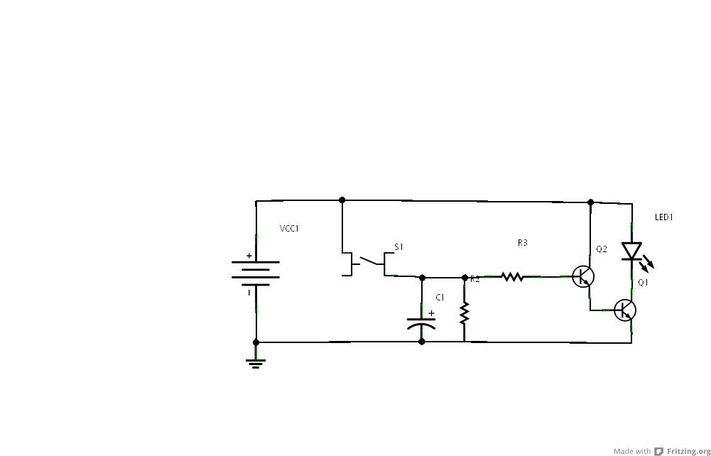
Then here’s the schematic:

And then here’s the PCB layout:

(Well, as you can see, I need to do some more work, but at least we’re getting there.)

Good points:

(1) It’s pretty.

(2) Very intuitive. I was able to do this much within an hour or so, without using the tutorials.

(3) Once you have the PCB ready, you’re only a few clicks away from sending it to a manufacturer and having physical mass production!

Bad points:

I don’t know enough about Fritzing to say anything bad about it. It was easy to download, didn’t crash or glitch. Wish I could say as much about some software that I’ve paid good money for.

I will say that I made a schematic of the circuit, then went to breadboard view, and it was a tangle of wires. Then I tried the breadboard view first, and went to schematic, and again, a tangle. Likewise, the PCB view took some untangling too, which as you can see still isn’t undone.

But I’m expecting too much here. First, the program is free. Second, the program can’t second-guess the user as to the optimal placement of the components and so there’s no way to get out of that work. Third, maybe if I was better at making schematics and circuits, the tangle wouldn’t seem so intimidating. Fourth, I certainly can’t create PCB layouts on my own at this stage of my knowledge, so here the program is enabling me to do something that I can’t do otherwise. Fifth, maybe it would help to go through the tutorials (ya think?).

I should note that I used an LED in the circuit rather than a lamp because I couldn’t find a lamp symbol. You are able to create your own symbols, but I was too lazy to do that yet.

Another thing, if you’re expecting Fritzing to do a circuit simulation, well, it doesn’t. But programs that do circuit analysis have been around for decades, and if it’s not possible already, I expect at some point in the future it will be possible to export a Fritzing schematic into a file format that a dedicated circuit analysis program could load. So I agree with the development team that their focus should not be on circuit analysis/simulation but rather on streamlining the process from breadboard to PCB layout.

All in all, the program is fun to play with and if you’re working with circuits, you should give it a look at Fritzing.org.

Posted in Uncategorized | Tagged , , , , , , , , | 1 Comment

Autofade Lamp Test Circuit Upgrade

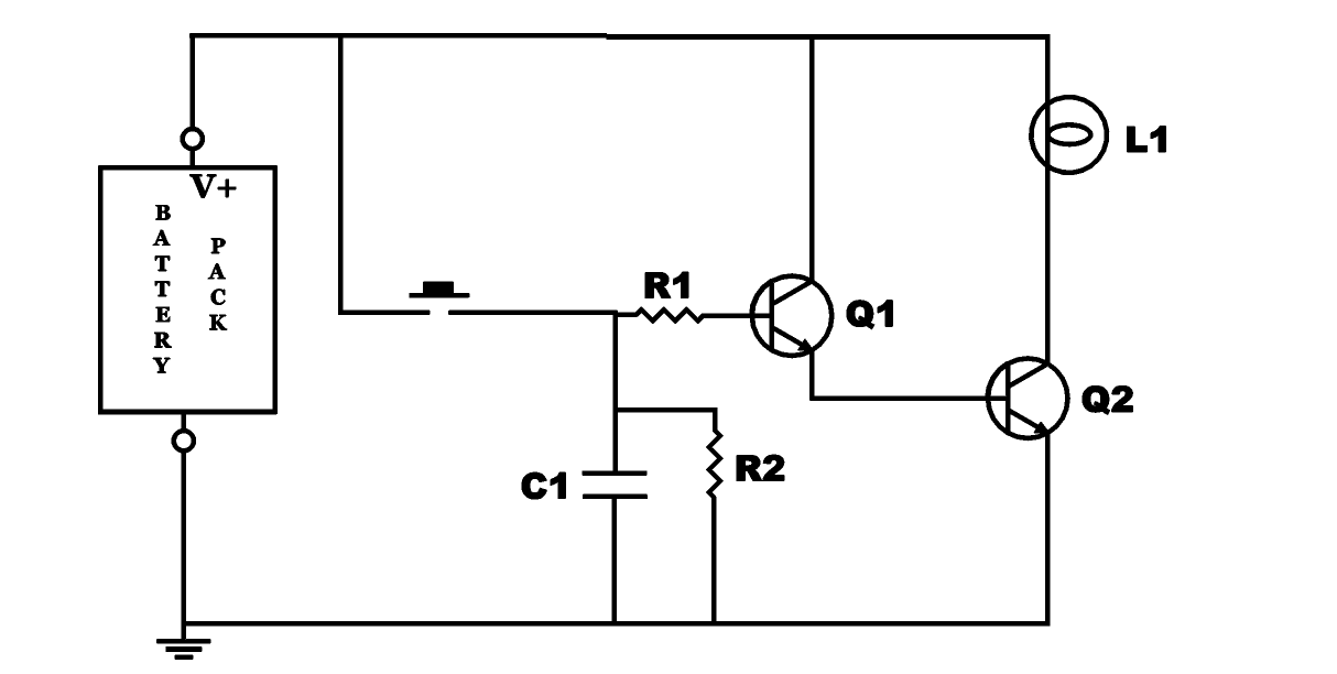
On Saturday, I reported that I didn’t have enough current gain in my autofade lamp test circuit to get a flashlight lamp to glow. The solution was to insert a second transistor, so that the circuit looks like this now:

This is presented in a second video in the autofade lamp series.

Here is the first video in case you missed it:

And here is the second video, about my adventures in upgrading the test circuit:

And so it might be time to start looking at enclosures, reflectors, and diffusers.

Posted in Uncategorized | Tagged , , , , | Leave a comment

Upgrading Autofade Lamp Test Circuit

Well, today was kind of discouraging. Here’s the new autofade lamp test circuit, upgraded:

And here’s the key:

A: I replaced the red LED with a flashlight lamp. The soldering operation was successful and the light is bright enough.

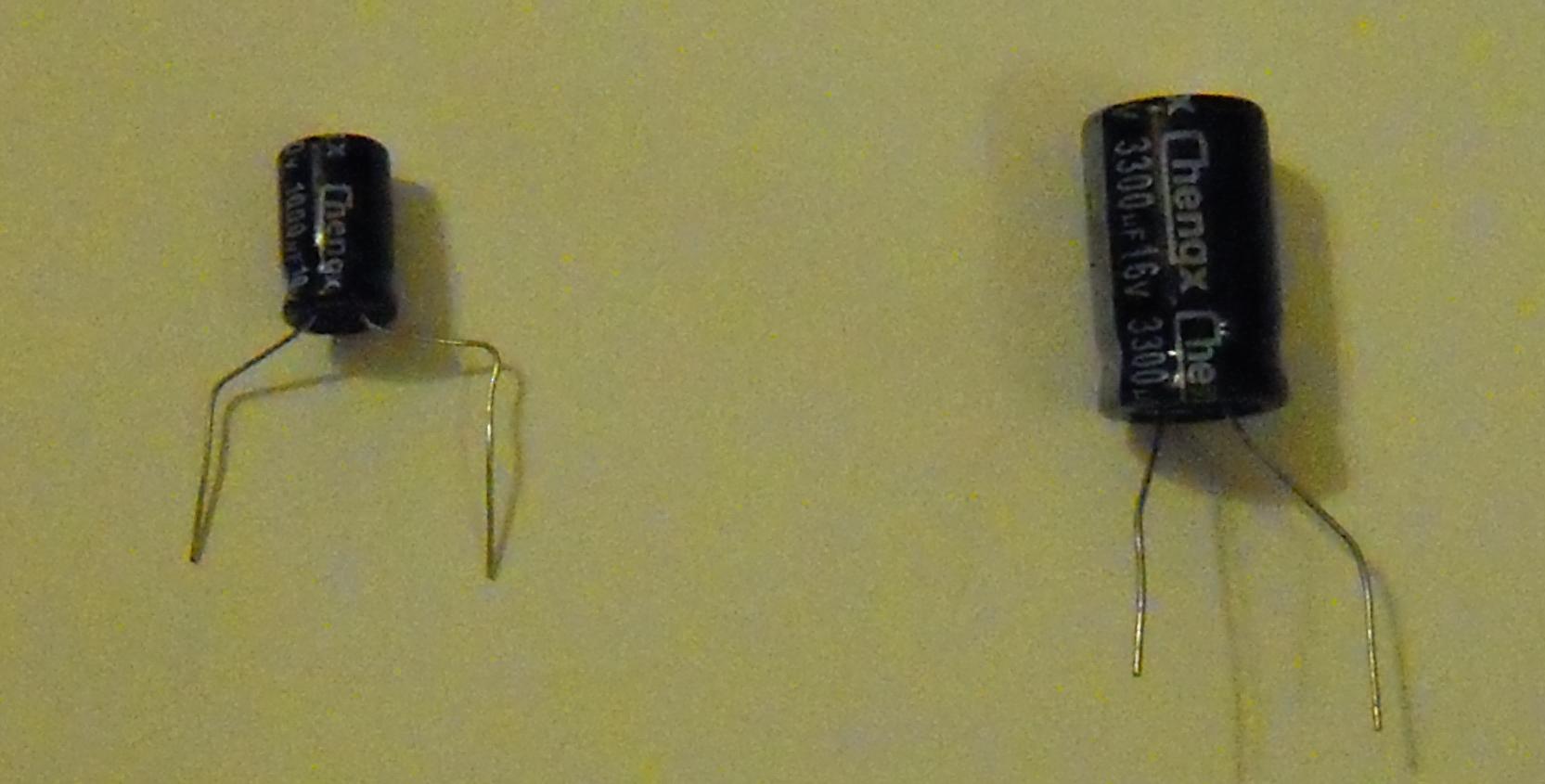
B: I upgraded the capacitor from 1000 microfarads to 3300.

C: The transistor got hot, so I swapped out the 2N3904 to a 2N4401.

And . . . it doesn’t work.

When the LED is swapped back in, the circuit works fine, but there’s not enough base current to amplify the collector current enough to light the lamp. And I do mean that I don’t even see a glimmer.

Where to now? Try a power transistor, try two transistors in piggy-back, try different resistance values. I’m sure there’s a way to make this work, but we’ll probably put it aside for a while because I want to spend some time brainstorming ideas for other future products and how to market them.

Maybe I should draw something in Sketchup. That’s often relaxing.

Posted in Uncategorized | Tagged , | 2 Comments

Upgrading Autofade Lamp Prototype

Okay, now it’s time to upgrade the autofade lamp from test circuit to product prototype. And so today was a shopping day.

First, I want to swap the 1000uF capacitor with a 3300uF to make the fade last longer.

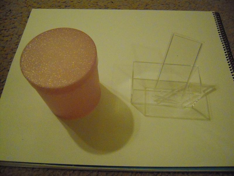
Next, I got a variety of enclosures from Michael’s arts and crafts:

Alas, pink was the only translucent in stock. The plastic box is for displaying matchbox cars. A little small, perhaps.

The cardboard box is the wrong material but the right size and shape. The orange thing is a mold for making sand castles, which suggests the possibility of making the lamp into the shape of a sculpture. It costs only a dollar.

This wooden box with glass sides was on the upper end, almost six dollars, but it suggested this could become an arts and crafts project. I would market the electronic innards and then people could put them in whatever enclosures they want, and decorate however they want.

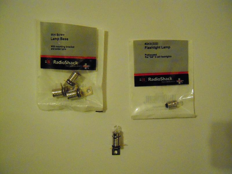
Last but certainly not least:

Here’s a flashlight lamp plus a holder. My nephew and I tested the lamp and it certainly is bright enough for our purposes.

Lights, capacitors, action plan — we’re on our way.

Posted in Uncategorized | Tagged , | Leave a comment

Autofade Table Lamp on Youtube

Here’s the autofade table lamp video that I posted to Youtube. Values of the capacitor and resistors are subject to tweaking, of course.

Posted in Uncategorized | Tagged , , , , , , , , , | Leave a comment

Autofade Table Lamp Test Circuit

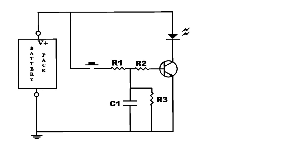
So, as you recall from my previous entry, I wanted to build an autofade table lamp based on this circuit diagram:

This is how the test circuit looks in reality (the hand, by the way, is my nephew’s):

This slideshow requires JavaScript.

(Note that resistor R1 in the schematic was omitted in the test circuit. Didn’t need it, turns out.)

So . . . did it work? Actually, yes. It doesn’t look like I have a photo of the LED lit when the button isn’t being pushed, but I did take video of that.

I’m going to put together a Youtube video soon that will include the raw video that I took of the test circuit in operation. Then we’ll move onto making a prototype.

Posted in Uncategorized | Tagged , , , , | 1 Comment