Having a Product

One day Steve Jobs was given a presentation by Apple engineers on the status of a major project. He listened, frowned, and replied, “We still don’t have a product.”

That’s the issue that has been haunting me the past couple of years. I have a robot, now I have a kit. But do I have a product?

A product is not just a collection of parts. It’s not just a collection of parts that function well together. A product is something that people want to buy.

A while back I honed my soldering skills with a ‘eurosiren’ kit. It was very informative, as far as learning to solder goes. But when I was done, I turned it on for about two seconds and then turned it off and put it away.

A soldering kit qualifies as a product, but I don’t think the same concept of a kit-for-the-sake-of-learning-by-making is going to work for little Grisbot. That eurosiren soldering kit only cost $15. Will users be satisfied spending $25 (or more) to build a robot that merely follows a preset path? I don’t know, for that price point I think people expect a greater level of functionality when they get done with it.

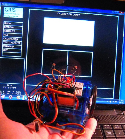
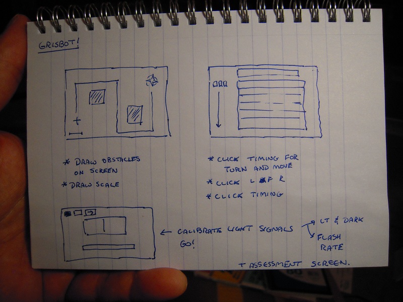
So today I was thinking, “Maybe I could make it into a game.” The idea is to draw obstacles on the screen, then make an obstacle course on a table (or hard floor). Presumably, the obstacles would be something like, but not necessarily, lego bricks. But merely drawing the path on the screen wouldn’t be enough. The robot has to be calibrated for turns and moves as well.

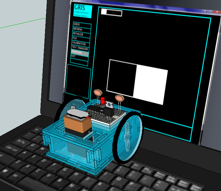
So I sketched out a multi-screen computer interface like so:
DSCN9768

Per the game aspect, points would be assigned according to the complexity of the course and how many tries it takes to program the robot correctly to complete the course. The computer-based program would communicate with the robot through screen flashes. It should be written in something easily accessible, like Scratch or the browser-based version of Processing. As for the microcontroller-based program, that would take a revision of what I have now, but not a big one.

If I can come up with a couple more gamelike elements, say like hooking a ‘prize’ and returning it to base, I might just indeed have a product.

* * *

So what happened to my intent to make a calibration routine? Well, manual trial-and-error calibration is going to be part of the game now.

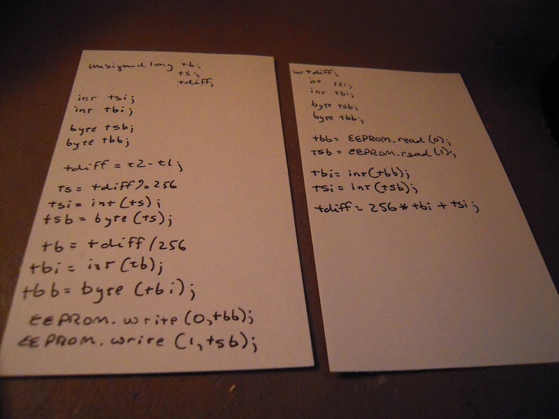
But just to let you know, I did do some programming on how to stuff calibration values into EEPROM so that they can be automatically retrieved and don’t have to be entered manually each time the robot is turned off and on. The main problem is converting variable types from unsigned long (for time measurements) into bytes (for EEPROM storage).

Here is the preliminary program I drafted, which I may yet get around to debugging and using:
DSCN9769

The tricky thing is to make sure the read/write commands don’t burn out EEPROM. The ATMega328 EEPROM is good for 100,000 cycles, which can last decades if you’re using the commands only once per program run, or it can last seconds if you accidentally include them in an infinite loop.

But I’m off on a new tangent, so maybe I won’t have to worry about that for now.
Posted in Uncategorized | Tagged , , | Leave a comment

Programming ATMega328 with Arduino platform

DSCN9628

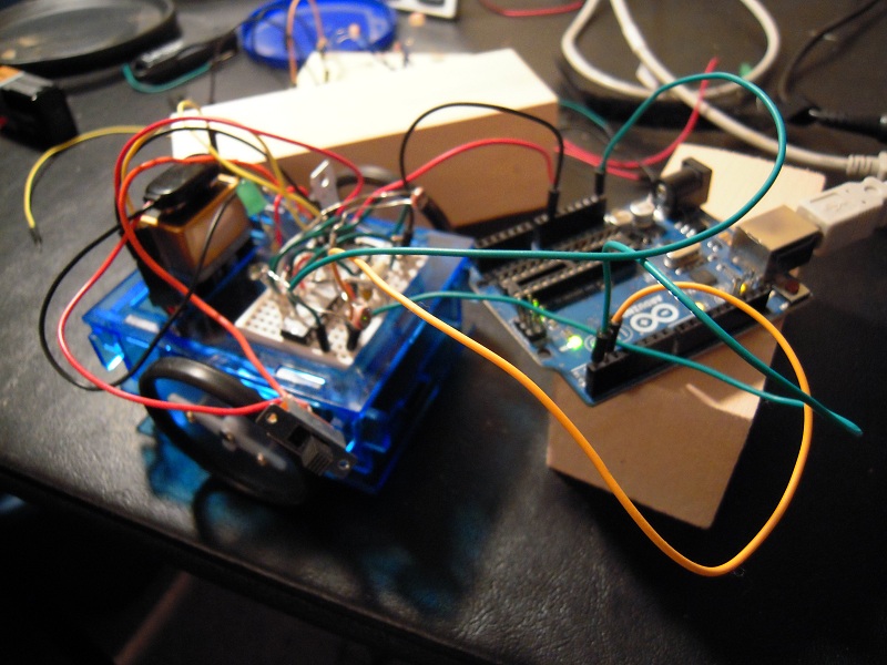
In theory, it’s possible to program the ATMega328 while it’s off the Arduino platform. Simply connect the Rx, Tx, GND, 5V and reset pins, and you’re in business. Well, it didn’t work for me and in the process I realized that connecting and disconnecting all those wires isn’t going to speed up the transfer process compared to simply moving the chip itself.

The picture shows the 5V line disconnected because otherwise the robot would be moving in accordance to its previous programming. I’m wondering if the servos are interfering with the data transfer process here.

Anyhow, there’s a lot of software troubleshooting left to go and I’m thinking that I need to revise the robot so that it can cradle an Arduino instead of just the ATMega. Once I get done with all the programming for the Arduino, maybe then I can go back to just using the chip.

BTW, the demo at the Seattle Robotics Society meeting seemed to go well, and a couple people came by and expressed interest. So I may have sales next month. That is, if I have a viable product by then.

Posted in Uncategorized | Tagged , , | Leave a comment

Rewiring the robot

BEFORE:

DSCN9019a

AFTER:

DSCN9506

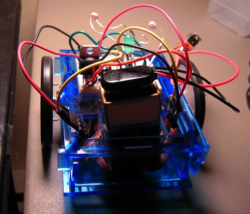
The robot simply stopped working. I had to strip everything down to the breadboard, then build back up again. Now it seems to be working once more.

Posted in Uncategorized | Tagged , , | Leave a comment

Assembly line for robots

DSCN9490a

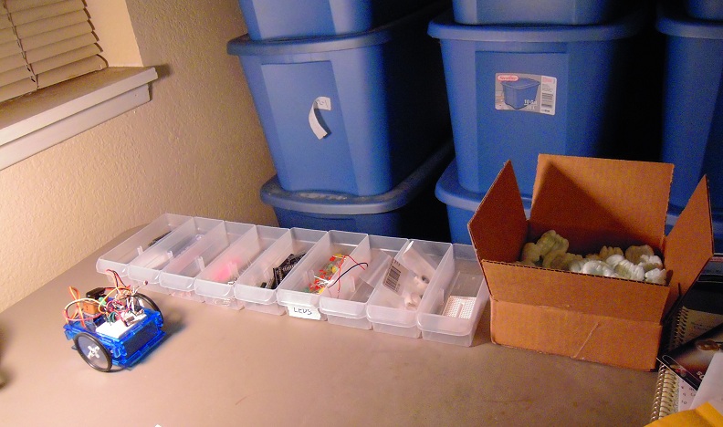
We hear all the time about robots on the assembly line. Well, here is an assembly line for robots.

As my experience as a temp taught me, every assembly line begins with bins full of parts. In this case, the ATMegas, voltage regulators, photoresistors, etc., that go into making my robot.

This picture is really ‘for illustration purposes only’ because I’m still working out what I need. For example, I don’t have the new servos I ordered, and when they come I’ll have to set up a work station to convert them to continuous rotation.

No place for the acrylic parts yet. I still have to wheel and deal to find a decent price for laser cutting. A personal laser cutter is a bit pricey, but thinkin’ ’bout it.

As the rat’s nest of wires hints, the robot design is far from finalized, and the steering pulls right and I don’t know what I’m going to do about that. But when it’s ready to go, I’ll have an assembly line ready around the same time.

Posted in Uncategorized | Tagged , , | Leave a comment

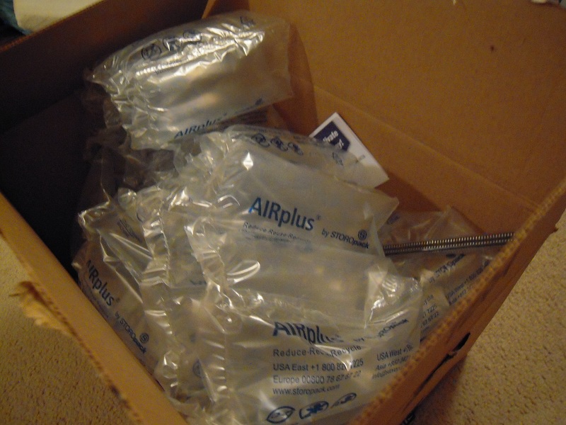
Amazon ships me a 99.6% empty box

DSCN9469

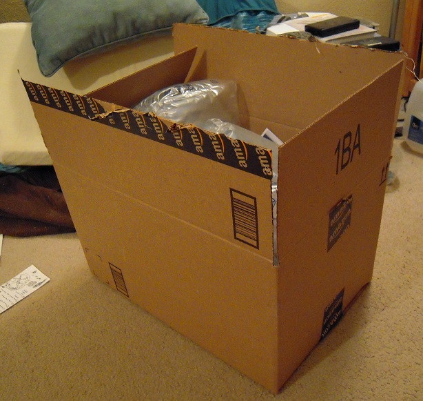
Wow, Amazon sure shipped me a big box today! Funny, I don’t remember ordering anything that big. Let’s take a look inside . . . .

DSCN9470

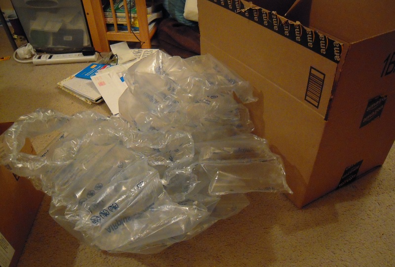
Well, there appears to be a lot of filler material. So I’ll take that out . . . .

DSCN9471

A LOT of filler material. It seems a shame that there is absolutely nothing I can do to put this stuff to use, so I’ll just have to throw it away. But at least it was necessary to protect all the contents, right? Right . . . .

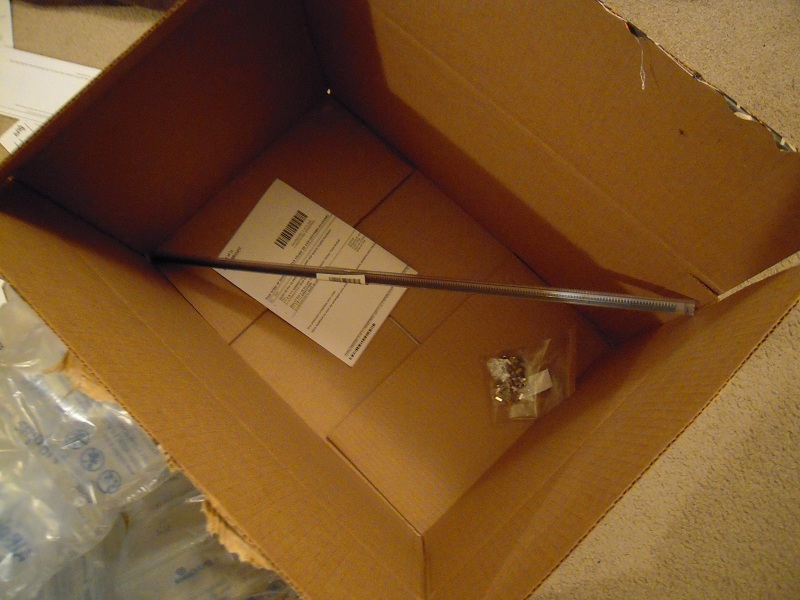
DSCN9473

And these are the contents. Apparently Amazon doesn’t have shipping tubes long enough for one of the two items, so they stuck it diagonally into a box big enough to fit. Never mind that 99.6% of the interior was empty. (Yes, I measured and calculated).

And this is the shipping cost relative to the whole order:

DSCN9474

Well, maybe I can find a good use for the box. It cost me enough.

Posted in Uncategorized | Tagged , , | Leave a comment

Using LEDs as Test Servos

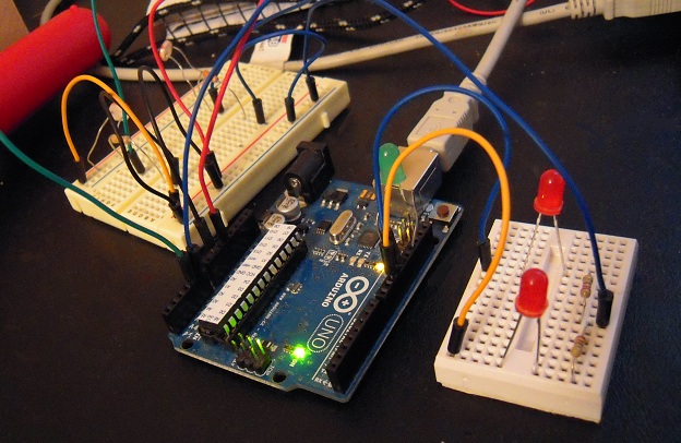
I fully intended that I would complete all software testing before I removed the ATMega chip from the Arduino even once. However, as I test the software, I’ve had to swap out the ATMega chip from the robot back to the Arduino prototyping platform many times.

I’ve gotten tired of returning the chip to the robot only to discover that the servos still weren’t turning, then having to move the chip back to the Arduino so I could reprogram it. So I set up this test rig attached to the Arduino, to take the place of the robot during on-board testing of the chip software:

DSCN9451

On the left are photoresistors, and on the right are two LEDs in place of servos. The LEDs are attached to the same pins that the servos attach to when the chip is on the robot, therefore when the command goes to the pins to turn on the servos, the LEDs light up instead. This tells me whether the programming is turning the servos on and off at the correct times.

Since the pins are PWM (pulse width modulation), changing the servo speed causes the intensity of the lights to vary too. It isn’t proportional, but an explanation as to why that’s the case would take too long and will have to be outside the scope of this blog entry.

Posted in Uncategorized | Tagged , , , | Leave a comment

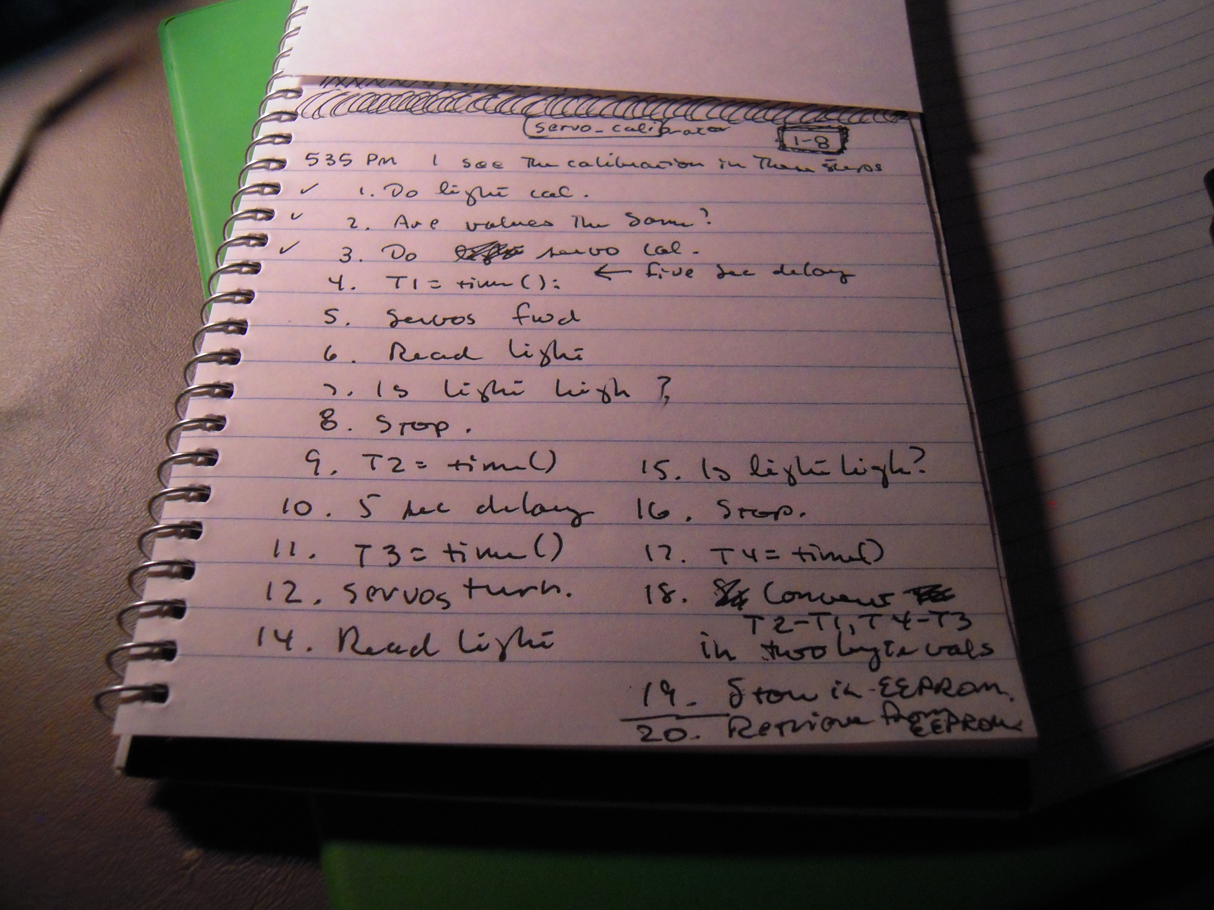
Programming the servo calibration procedure

DSCN9249

Sub program, sub routine, function, procedure — it seems like every programming language has a different name for ‘blocks of code.’ Well, now I need to write a block of code for the servo calibration procedure. So first I drafted the above procedure.

Then I modified the light calibration and main programs (functions, procedures, etc.) and created a servo_calibration() procedure. Here’s what part of that looks like:

  // activate the servos 
  myservo1.attach(11);
  myservo2.attach(10); 
 
  // servos move forward 
  myservo1.write(0);
  myservo2.write(180);
  
  t1 = millis();

  servo_calibration1:  
  
  v = analogRead(0); 

  if (v<700){
    goto servo_calibration1;
  }  
  
  t2 = millis();
  

The photo shows check marks to 3 but I’m actually down to step 17. Just have to do EEPROM and I’ll be on my way to ‘field testing.’

(NOTE: this configuration initiation procedure is different than the one I came up with a couple days ago. I’ll show how it works when I get it running.)

Posted in Uncategorized | Tagged , , , , | Leave a comment

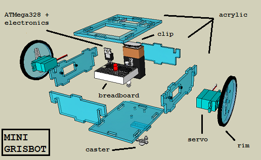
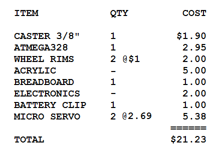
Grisbot Bill of Materials

exploded

How much do the materials of the robot cost?

billofmaterials

Costs not included: laser cutting service, switch, labor for servo conversion and pre-soldering (if any), hardware (ie bolts and nuts).

Posted in Uncategorized | Tagged , , | Leave a comment

Mini gris servo calibration mode

The robot ‘brain’ (aka ATMega328) needs to know how long the servos must rotate in order to properly execute moves and turns. Hence there must be a servo timing calibration mode, and a way to initiate the mode. I’ve toyed with using a pushbutton or a magnet/reed switch in the past, but then the obvious occurred to me: why not just have a calibration mode control code?

gris_config1

Instead of sending path segment angle and distance information, the GRIS program will simply flash a single control code. I’m leaning toward ‘124,’ since 125 and 126 are the start and stop control codes.

gris_config2

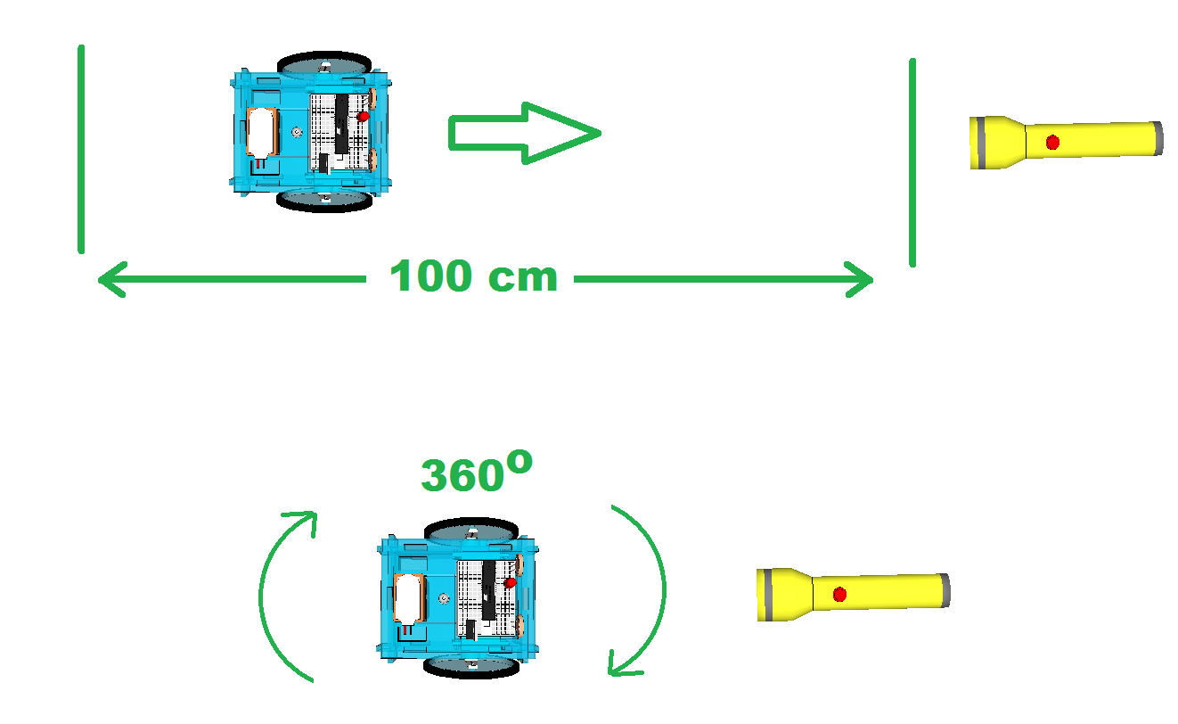
In servo timing calibration mode, the robot will wait five seconds and then start traveling in a straight line. It is up to the user to measure out a distance of one meter and to shine a flashlight on the photocells when the robot reaches that distance. At which point the robot stops and stores the calibration information in EEPROM.

After another five seconds, the robot will start turning. After it has turned full circle (ie, 360 degrees), the user shines the flashlight again, and the robot stops and again stores calibration information in EEPROM.

Now the robot knows how long it takes for the servos to travel one meter and turn 360 degrees, and from that it is easy to calculate how long it will take to travel one centimeter and turn one degree. The next time the robot is turned on in regular mode, it will reference EEPROM and retrieve the stored calibration values, and multiply the path distance and turn data by the unit amounts to calculate how long the servos must rotate for each command.

No magnets or reed switches required, but I will have to revise the main GRIS program. This will keep me busy while waiting for ordered parts to arrive.

Posted in Uncategorized | Tagged , , , , | Leave a comment

Moon Mission 2

A company called Golden Spike is planning to offer manned missions to the Moon by the end of this decade. Here is their graphic:

Learn about Golden Spike Company's plan to land paying astronauts on the moon by 2020, in this SPACE.com infographic.
Source SPACE.com: All about our solar system, outer space and exploration

Here is a video essay that I did on the subject almost two years ago:

Posted in Uncategorized | Leave a comment