
I fully intended that I would complete all software testing before I removed the ATMega chip from the Arduino even once. However, as I test the software, I’ve had to swap out the ATMega chip from the robot back to the Arduino prototyping platform many times.
I’ve gotten tired of returning the chip to the robot only to discover that the servos still weren’t turning, then having to move the chip back to the Arduino so I could reprogram it. So I set up this test rig attached to the Arduino, to take the place of the robot during on-board testing of the chip software:
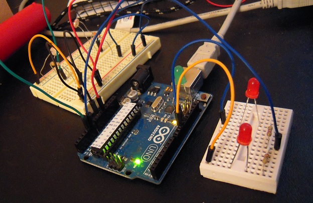
On the left are photoresistors, and on the right are two LEDs in place of servos. The LEDs are attached to the same pins that the servos attach to when the chip is on the robot, therefore when the command goes to the pins to turn on the servos, the LEDs light up instead. This tells me whether the programming is turning the servos on and off at the correct times.
Since the pins are PWM (pulse width modulation), changing the servo speed causes the intensity of the lights to vary too. It isn’t proportional, but an explanation as to why that’s the case would take too long and will have to be outside the scope of this blog entry.
