Light Follow Test Rig

DSCN2403

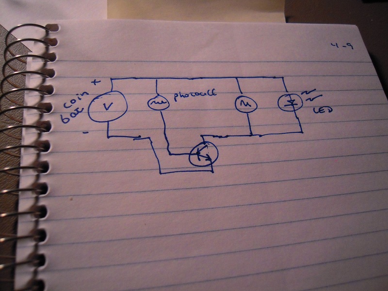
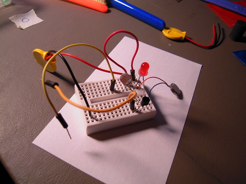
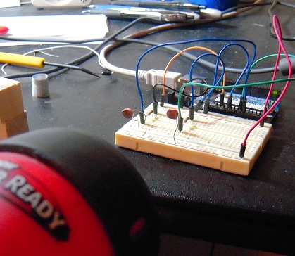
With this test rig, I plan to write a sketch for grisbot that will cause the robot to follow a flashlight beam. There will be two states, Triggered and Non-triggered. The transition to from N to T occurs at a value of 500 on the analog input port, while the transition from T to N occurs at 250.

The user will hold a flashlight up to grisbot, and if the value exceeds 500, the robot will do a brief 1/4 sec sweep side to side, then head toward the direction that has the maximum value of light. Every couple of seconds, the robot stops and does another sweep, then re-orients. This continues so long as the value remains above 250. If the value falls below 250, the robot enters the N state and stops. Every ten seconds, however, it will conduct a full circle sweep, and if it finds a value above 500, it will enter the T state and head off in the direction of maximum light.

Actually, that’s one possible mode of operation. I’m thinking of a couple more. I hope to fit them all in the same sketch with the path programs, so that everything can be activated via screen flash.

Posted in Uncategorized | Tagged , , | Leave a comment

Mic Check, some progress

mic check

On the left is a swatch of code that I wrote to read the analog input from the microphone circuit and print it to the serial monitor. On the right is the serial monitor.

Under normal circumstances, the value read at analog pin 1 hovers close to a value of 536. This constitutes ‘quietness,’ and no value is sent to the serial monitor.

Then I took a pair of wooden blocks and clacked them together a couple times over the microphone. That’s when the readings appeared on the serial monitor.

So the circuit works, though I’m not sure it works well enough to work as a room noise monitor. I hope it’s just a matter of tweaking resistor and capacitor values. Another thing, I’m testing this late at night in my apartment, so I can’t very well test it with some really loud, continuous noise lest the neighbors complain.

At any rate, I have other things to do at the moment and will have to put aside this project until next week, when I hope to test and tweak the system under ‘field’ conditions.

Posted in Uncategorized | Tagged , , | Leave a comment

Noise Meter Challenge

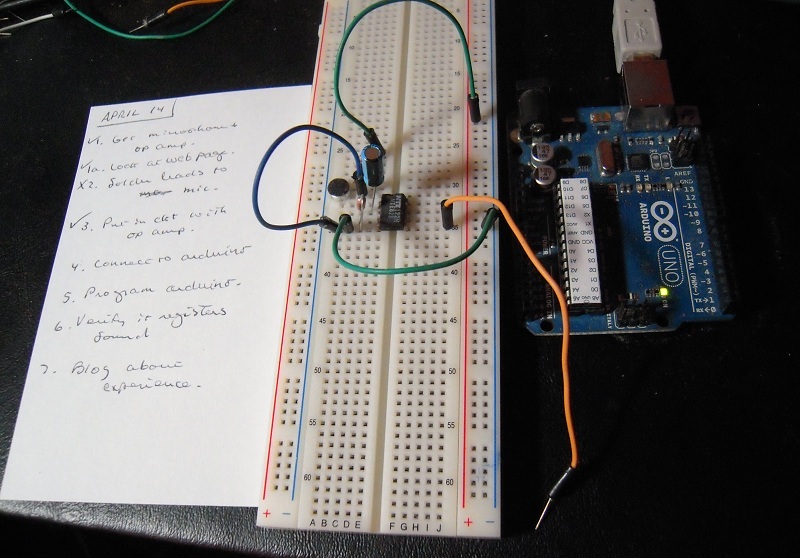
The Big Brained Superheroes Club has issued a challenge to build a noise meter, and so I thought I would give it a try. Hence I looked up a web page at the arduino site for building a noise meter. Note the schematic on the page, which I tried to implement here:

DSCN2298

As you can see from the checklist and the circuit itself, I’m about halfway finished and need to connect to the Arduino board, load in the sketch from the web page, and away we go.

— One tiny little problem, though. The aforementioned circuit diagram uses an LMV324 op amp, and the only one I could get on short notice was an NTE823. So I may have to tweak things a bit. That won’t break anything, will it?

Posted in Uncategorized | Tagged , | Leave a comment

Lessons Learned This Past Week

1. Cut the capacitor leads short so they won’t accidentally touch the photocell leads.

The design looked cleaner in the schematic.

The design looked cleaner in the schematic.

2. Fresh batteries make a big difference.

I can quit any time.

I can quit any time.

3. When masking tape is used to mark waypoints, a pipe-cleaner skid is prone to snag.

Swing your partner round and round.

Swing your partner round and round.

4. Do not make a video of a computer screen with the camera positioned on the same side and level as the mouse.

It wasn't in the way when it was adjusting the camera shot!

It wasn’t in the way when it was adjusting the camera shot!

5. Having ideas and having marketable ideas are two different things.

I got tired of paying a premium for coin batteries, that's why.

I got tired of paying a premium for coin batteries, that’s why.

6. Value the little things in life.

Oatmeal, yum!

Oatmeal, yum!

Posted in Uncategorized | Leave a comment

Programming the ATTiny45

About a year and a half ago, Matt Richardson did a video on how to ‘shrinkify’ your Arduino projects with the ATTiny chip. It was a very interesting idea that I finally got around to doing on Friday.

Here’s what the setup looks like when the Arduino is used as the ISP programmer for the ATTiny45:
DSCN2217

And yes, I tried the blink sketch, like so:

DSCN2218

So you don’t need an Arduino, or even an ATMega328, to blink an LED. You can do it with just an ATTiny, which is cheaper and doesn’t require supporting voltage regulator, capacitors, and crystal.

And here is something slightly more impressive:

Posted in Uncategorized | Leave a comment

Grisbot Hoop Capture Test

I’ve got a bad feeling about this.

DSCN2145

Before we begin, some brief technical details:

DSCN2140

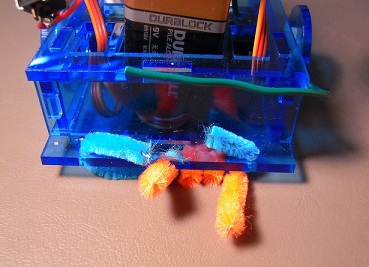
The orange pipe cleaner provides friction to compensate for servo swerve.

***

DSCN2142

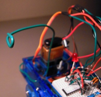
The catcher is just a piece of wire. Nobody likes overengineering.

***

DSCN2143

More equipment used in this highly scientific testing of the Graphical Robotic Information System. Did I mention I plan to sell kits?

***

And now the video of the test. WARNING: Not for the faint of heart!

Posted in Uncategorized | Tagged , , , | Leave a comment

Grisbot: 2-obstacle course

Starring Metric Blue:

Posted in Uncategorized | Leave a comment

Variations on a brushbot

DSCN2084

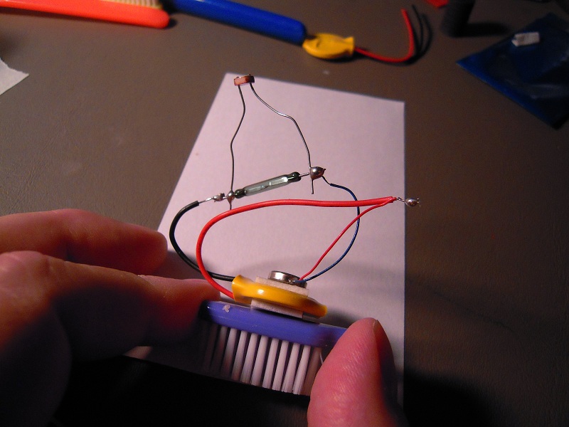
In my continuing efforts to find a simple product to market, I thought, “Why don’t I make some upgrade mods to the conventional brushbot?” So I ordered a brushbot kit from Maker Shed, and modified as shown. The long green component is a reed switch, which is activated by proximity to a magnet. There is also a photo cell in parallel, so that the brushbot can also be activated by a light source.

How well does it work? Not very, either way.

If the magnet is ceramic, the reed switch won’t activate unless the magnet is touching. If the magnet is rare earth, it snaps to the reed switch so fast that it ends up touching whether you wanted it to or not. The hope of being able to activate the robot at a distance with the wave of a magic (= magnetic) wand is apparently not to be.

As for the photocell, it does not permit enough current to run the motor, even in the brightest light. So I made a design to include a transistor as amplifier:

DSCN2087

DSCN2086

And how well does it work now? Too well. Even in the dimmest light, the motor runs at full speed.

I have ordered some ATTiny45s which will be here by Friday. With a microcontroller, it should be possible to read the photocell and adjust the motor accordingly. Also, I might be able program some interesting behaviors into the brushbot, maybe even steering (I understand it’s all a matter of shifting weight).

Imagine being able to program ‘dances’ and ‘tunes’ into the brushbot via PC, tablet, or smartphone app.

Posted in Uncategorized | Tagged , | Leave a comment

Weighing Robotics

Some weights that are interesting to know.

9v_wt

Display has one decimal place, so that 442 = 44.2. The display does have a decimal point, but it doesn’t show at the angle of the photos. Sorry.

arduino_wt

This is an Uno R3. I don’t suppose the old Uno weighs much different.

minigris_wt

The weight of the block has been tared, in case you were wondering if I forgot, which I have been known to do.

Interesting conclusion: Adding an Arduino (not including trays) will increase the mass of the robot only by less than 20%.

Posted in Uncategorized | Tagged , , | Leave a comment

Grisbot with Arduino

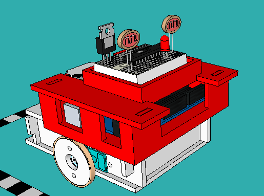
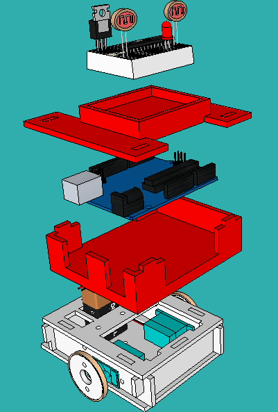
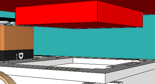
Here is a preliminary design of a dual tray assembly that can carry both an Arduino and a mini bread board:

gris arduino

gris arduino 02

Here’s an underview, showing how it all fits onto the robot body:

gris arduino 03

As is, the tray assembly can’t be made from laser cut parts. I’ll have to think about that. At any rate, I need something like this if I want to reprogram the robot without having to continually move the chip back and forth from the Arduino to the breadboard.

I wonder if there would be a market for the robot plus tray assembly. The robot kit would actually cost less than the Arduino!

(You’ll notice that the illustration shows an ATMega chip on the breadboard. Of course, if you have an Arduino, why do you need a chip on the breadboard?)

Posted in Uncategorized | Tagged , , | Leave a comment