Budget Arduino Robot Upgrades

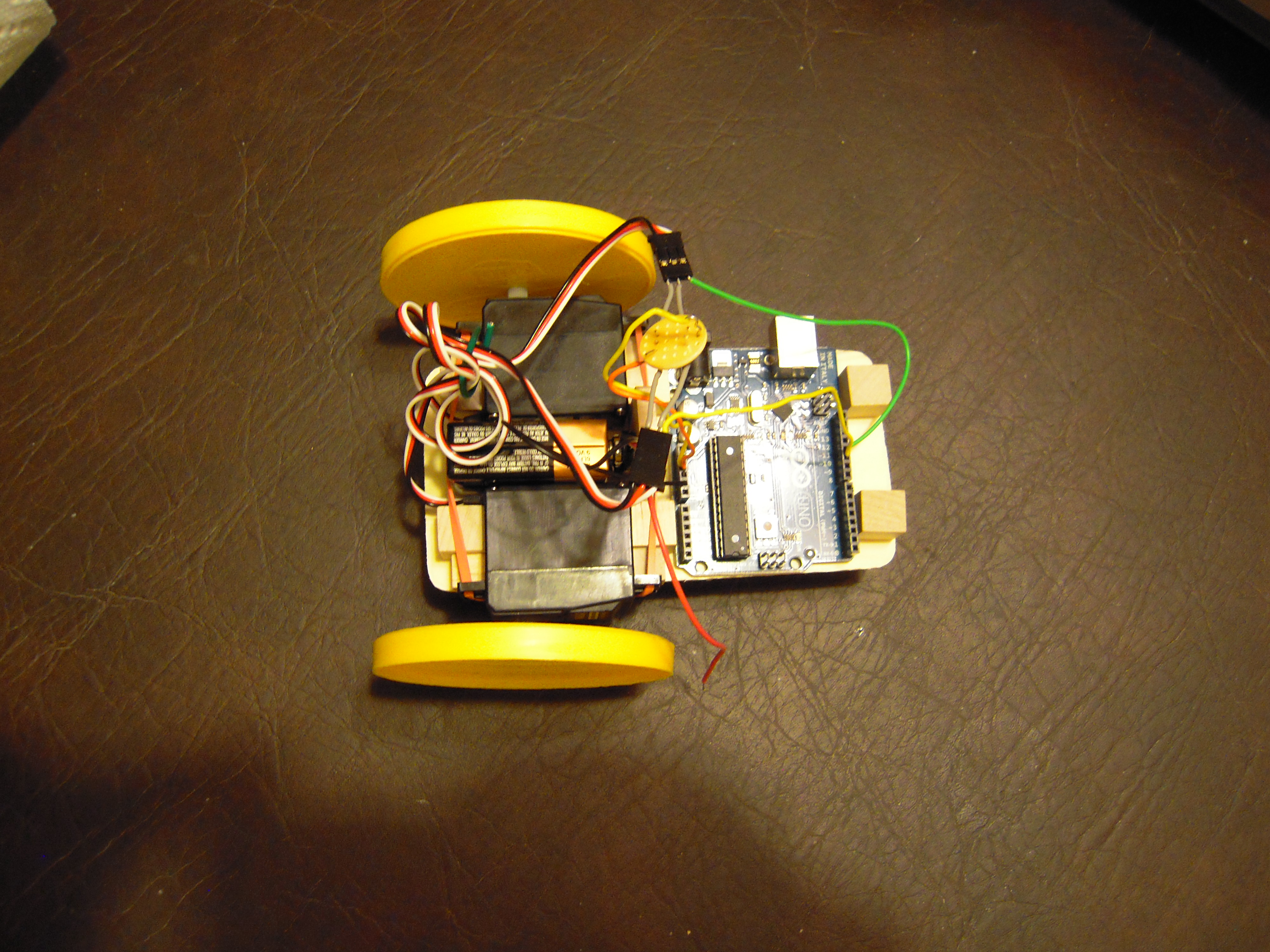
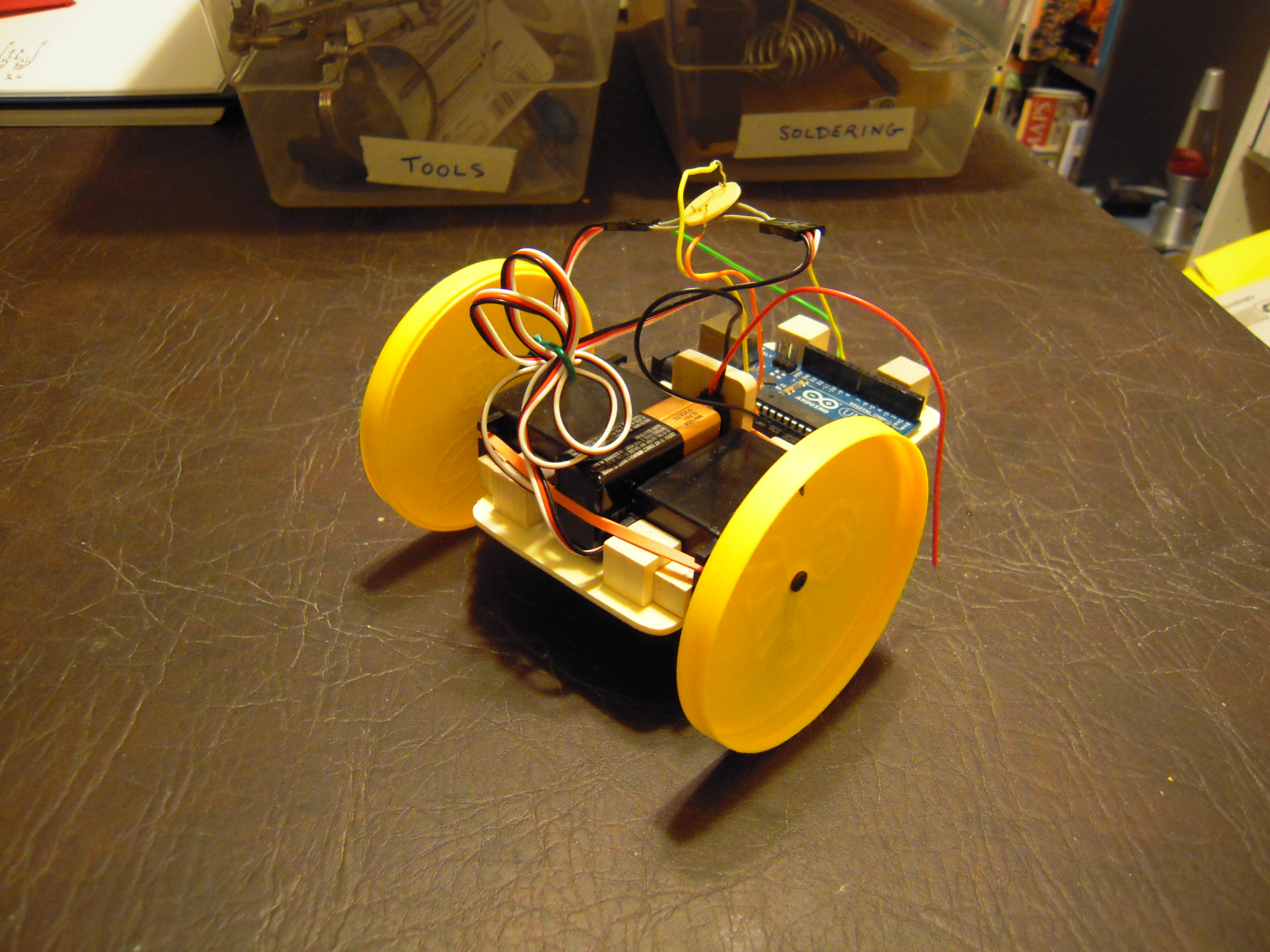
I’ve done some upgrades to my arduino robot. The change that seemed to help the most in the accuracy department was to upgrade the wheels. The potato chip container lids were kind of flimsy, so I replaced them with hard plastic iced tea jar lids.

I used a handheld electric drill to bore holes in the center of the lids. The drill was bought at Michaels on sale for $20. It’s not much but it got the job done.

The new wheels are much wider and have grooves, so that traction is good enough to run on the carpet now. I used pieces of cork to secure the screws to the wheels. I don’t know if that helps, but it seemed like the right thing to do.
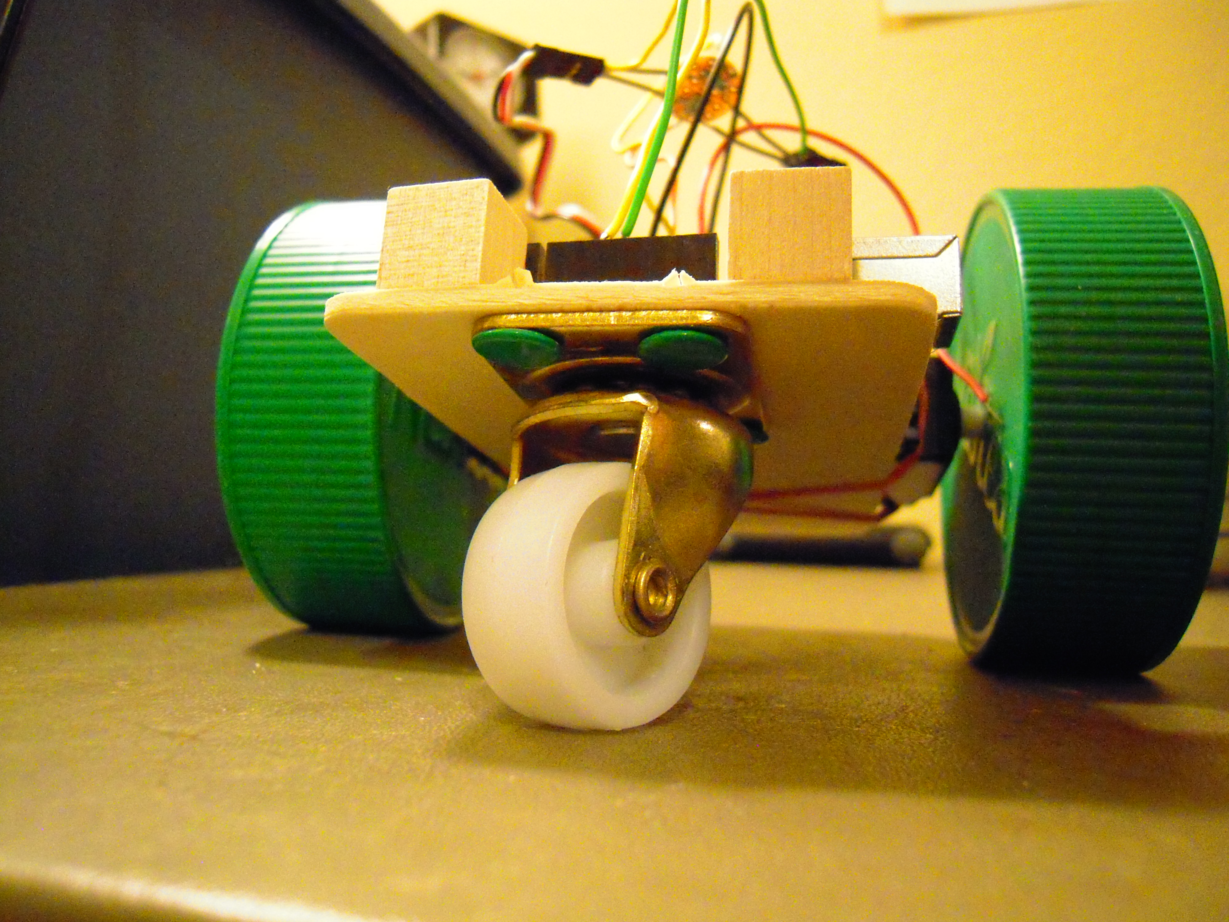
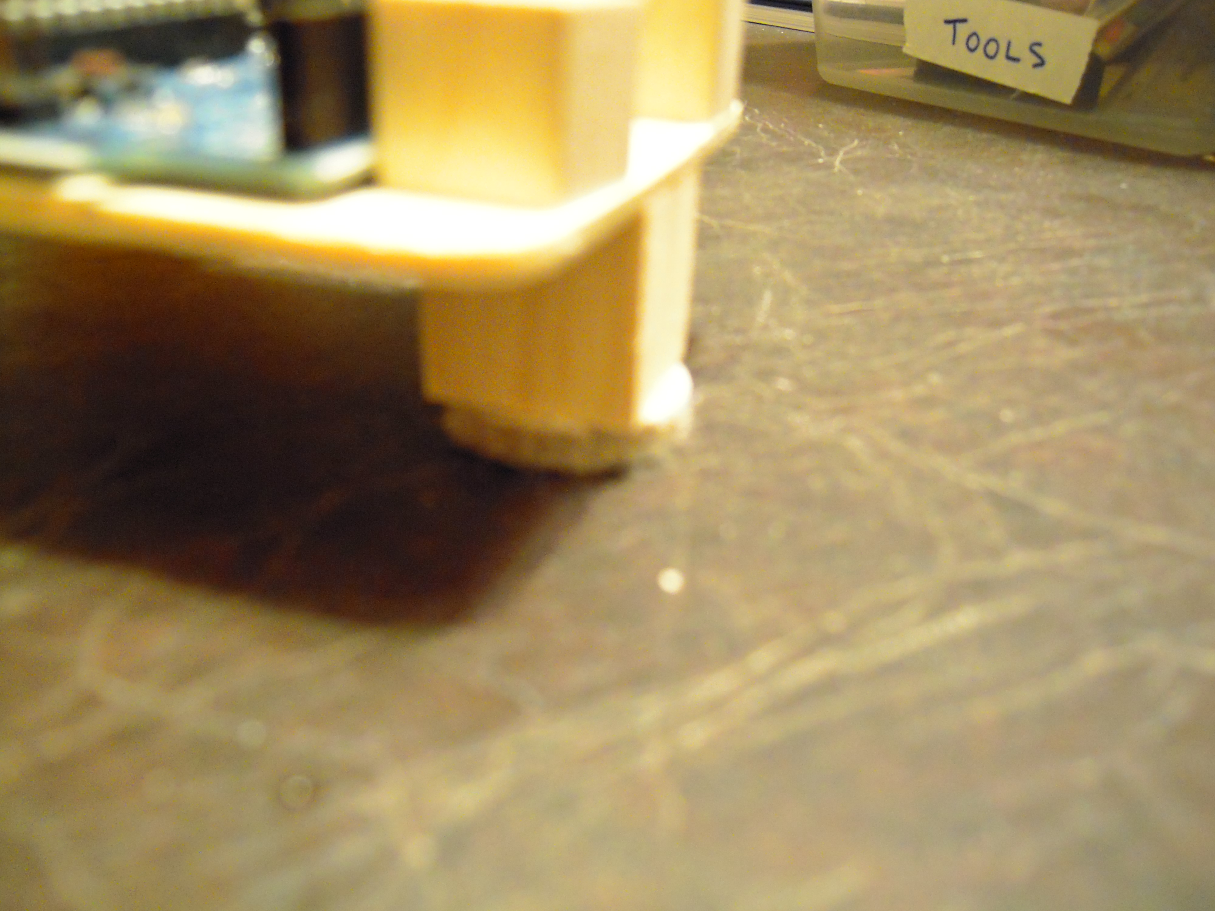
Also I put in a caster. One nice thing about using ordinary glue in a prototype is that it was easy to snap off the furniture-glider post in the previous version in order to put in the caster. Note, however, the caster is secured with thumb tacks.

A pair of casters costs about five dollars from Ace Hardware. No slight to Ace, but I’m still looking for a smaller, lighter caster as this one doesn’t seem to swivel responsively enough for the desired turn accuracy.
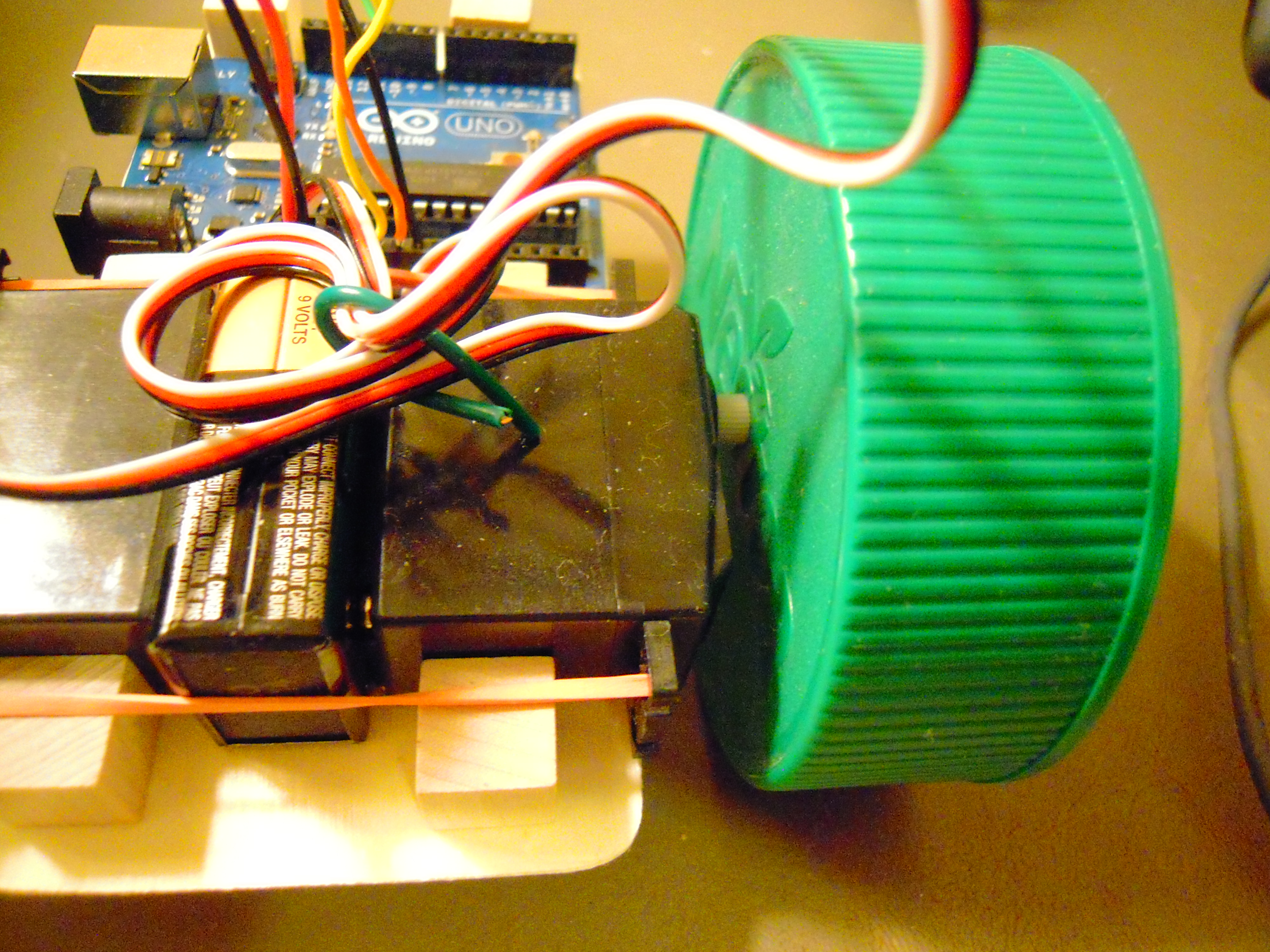
Another change I’m testing here is to flip the servos so that the wheels are more toward the center of the platform. Doesn’t seem to make much difference other than minor reprogramming.

All right, so here’s the video of the robot attempting to make a square path:

I need to tweak the turn period some more. In that regard, I tried to slow down the servos during the turn phase and the servo.write() function didn’t scale the way I expected. We’ll work on it.

And finally, there’s nothing informative about the following picture, but I’m tempted to glue toy eyes on those little cubes in front:
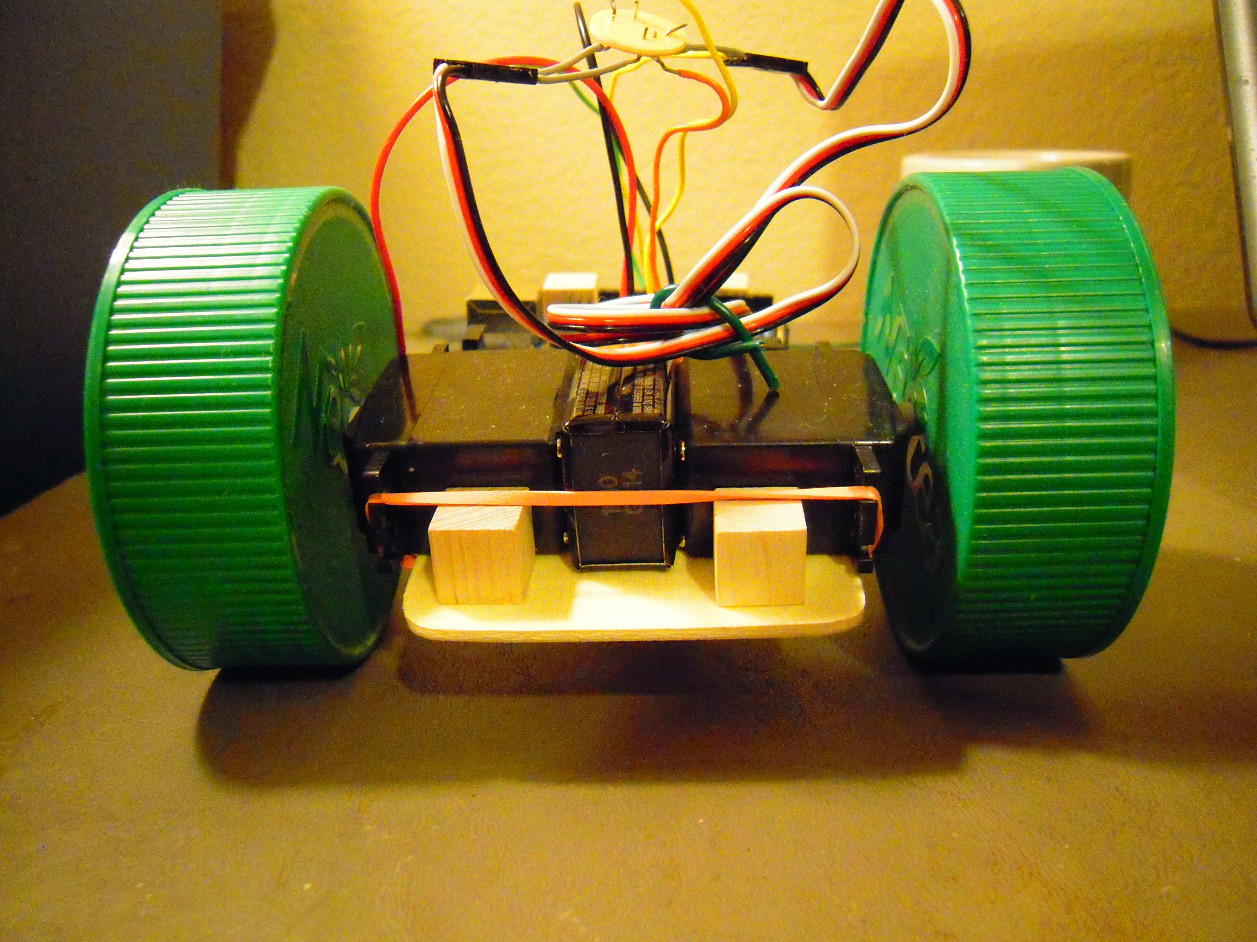
(Or maybe LEDs should go there?)
Posted in Uncategorized | Tagged , , , | 3 Comments

Budget Arduino Robot Project

Given the problems that I was having on using GIRC (Graphical Interface for Robotic Control) with RC toys, I decided to build my own Arduino-controlled servo-driven robot. Aside from the electronics, the body probably cost less than five dollars. A substantial savings over Arduino-compatible mobile platforms that can run fifty to over a hundred dollars!

It uses an Arduino Uno, which is powered during programming by the USB cable and during navigation by the nine volt battery, whose inputs go into Vin and GND (both on the left as seen here). Battery power is sufficient to drive both servos at half-speed from the 5v and GND. On the right, the servo control lines plug into pins 10 and 11.

Note that in the picture, the red power wire is not connect to Vin. That basically is the kludge for turning the robot off until I install a switch.

The wooden parts are glued together with ordinary Elmer’s white glue. I think the wood is balsa. I got the platform and the cubes from Michael’s Crafts. I wonder how many people shop for robot parts at an arts and crafts store. I’ve been wondering about using Lego parts instead. Perhaps a visit to the Lego Store is in order.

The wheels are simply the lids off potato chip containers. The containers cost $1.50 each, but the real cost (if you know what I mean) is that I felt obliged to eat the chips. Anyhow, the wheels turn okay but it looks like they need something to serve as nuts/washers. Perhaps pieces of cardboard would do.

This is the part that I’m least satisfied with. I just could not find an appropriate swiveling wheel despite an exhaustive search of Michael’s, the Goodwill toy section, and a hobby shop. I ended up using a wooden cube with a felt furniture ‘glider.’ How well does it work? Not very. It unbalances the turning depending on the friction of the surface and prevents the bot from moving on the carpet. I’ll keep looking for a pivoting wheel, which I have learned is called a ‘castor’ (also spelled ‘caster’).

This is the one component that required soldering. Each servo has a power and ground wire, but the Arduino has only one port each for them to go into. Thus I had to solder two ‘Y’ wire connectors on a perf board. I suspect I originally inserted the wires into the perf board the wrong way, but it still works.

I could have used a breadboard and probably will in future prototyping, but that would have added several more bucks to the overall robot cost, which I wanted to keep low here. Alternately, I was thinking of metal clips, but this seemed more secure. I’m sure there are a lot of ways to attach three wires together.

Well, there you have it. Wood, rubber bands, glue — truly a low cost, easy to assemble mobile robotics platform for the Arduino. Now if I can just get it to navigate accurately and be easily programmable from GIRC, I just might be on the way to building something that could be marketed on the internet as a kit.

Posted in Uncategorized | Tagged , , , , , , | Leave a comment

Seattle Maker Faire: The Case for Magnuson Park

(NOTE: The Seattle Mini Maker Faire will be held at the Seattle Center on June 2-3, 2012. For more information, please visit the official web site at makerfaireseattle.com. As for this blog entry, I like the pictures of Magnuson Park so I’m keeping it published for now, but be sure to read the comment which explains why the faire can’t be held there — at least not for this year.)

There’s been discussion lately of having a Maker Faire in Seattle in 2012. The question now is where to hold the event. I suggest Magnuson Park.

Long ago, Magnuson Park used to be the Sand Point Naval Air Station. It is situated on the Northwestern shore of Lake Washington. Although it is ‘tucked away,’ so to speak, it’s not hard to find. You get off 520 (ie Evergreen Point Bridge) at the University of Washington stadium, then drive north along the arterial that follows the lake. About ten minutes later, it’s on your right.

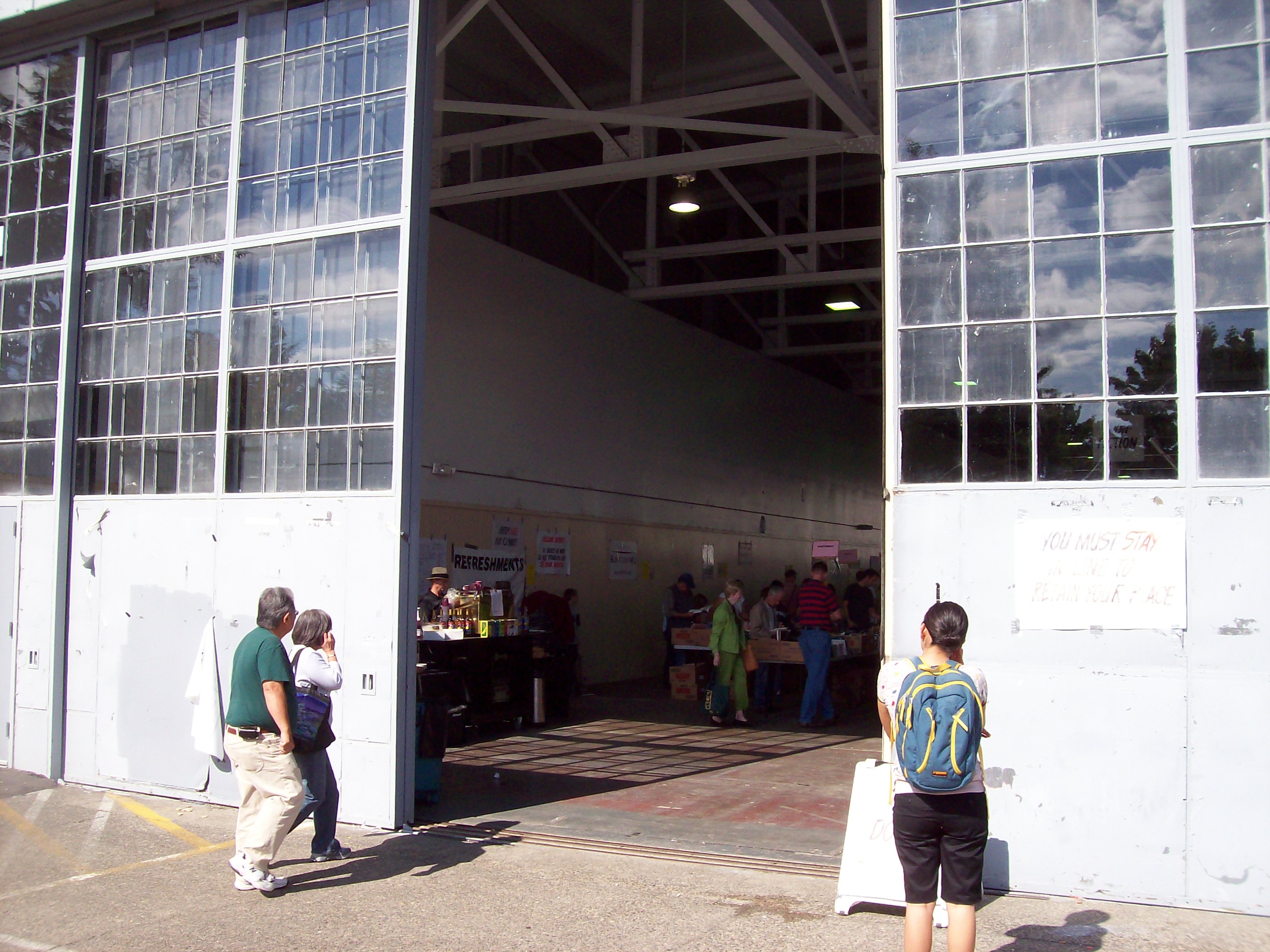
Magnuson Park has huge former airplane hangers that would easily accomodate the dozens of tables and demonstration areas needed to faciliate a Mini-Maker Faire.

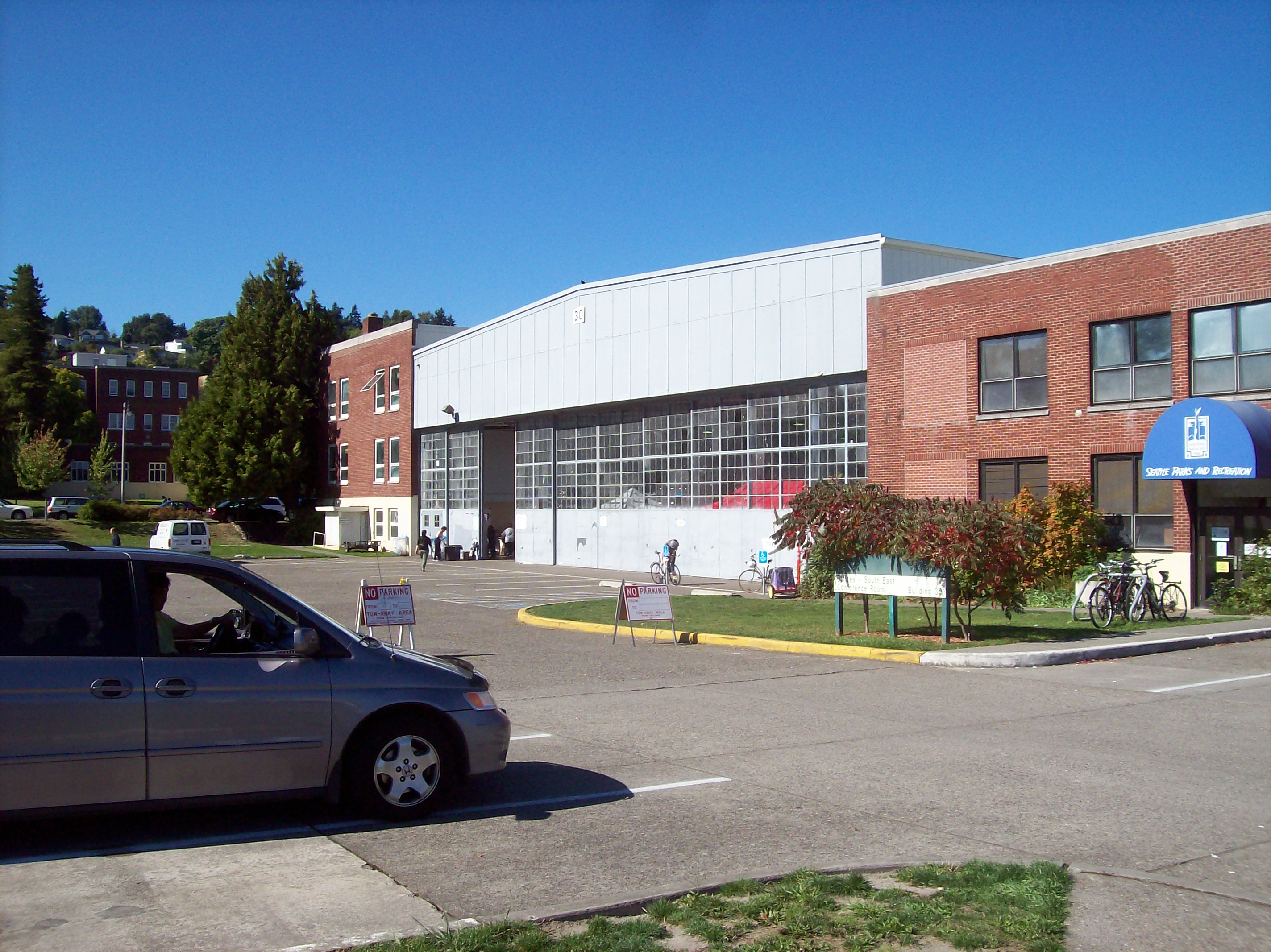
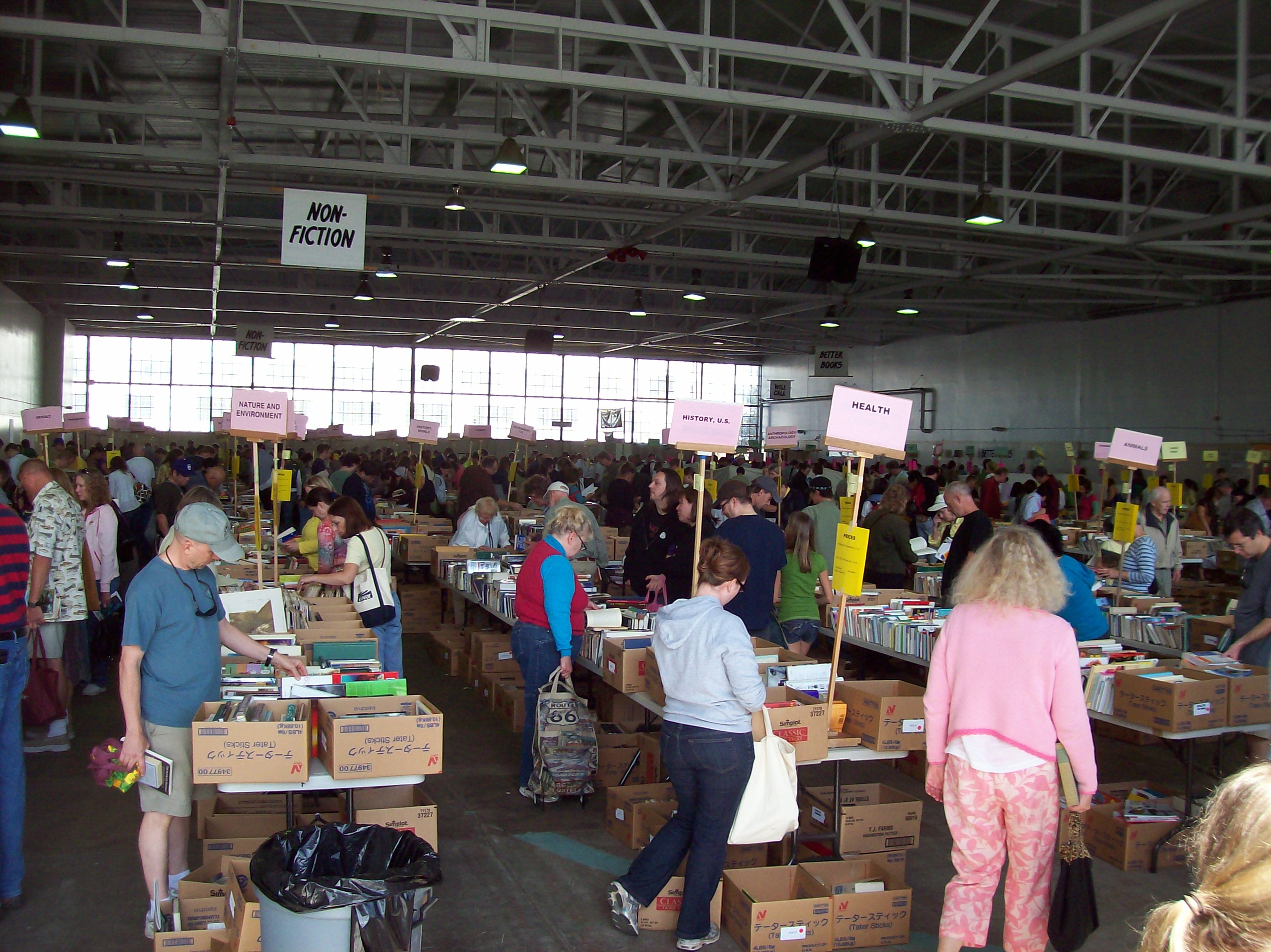
The Seattle Friends of the Library hold a semi-annual booksale there, and here’s the hanger that they use, which itself should be able to accomodate a Mini-Maker Faire (with potential in the rest of the park to host a full fledged version):

Magnuson Park is a good match for Maker Faire, because it has already got to be one of the geekiest parks in the world.

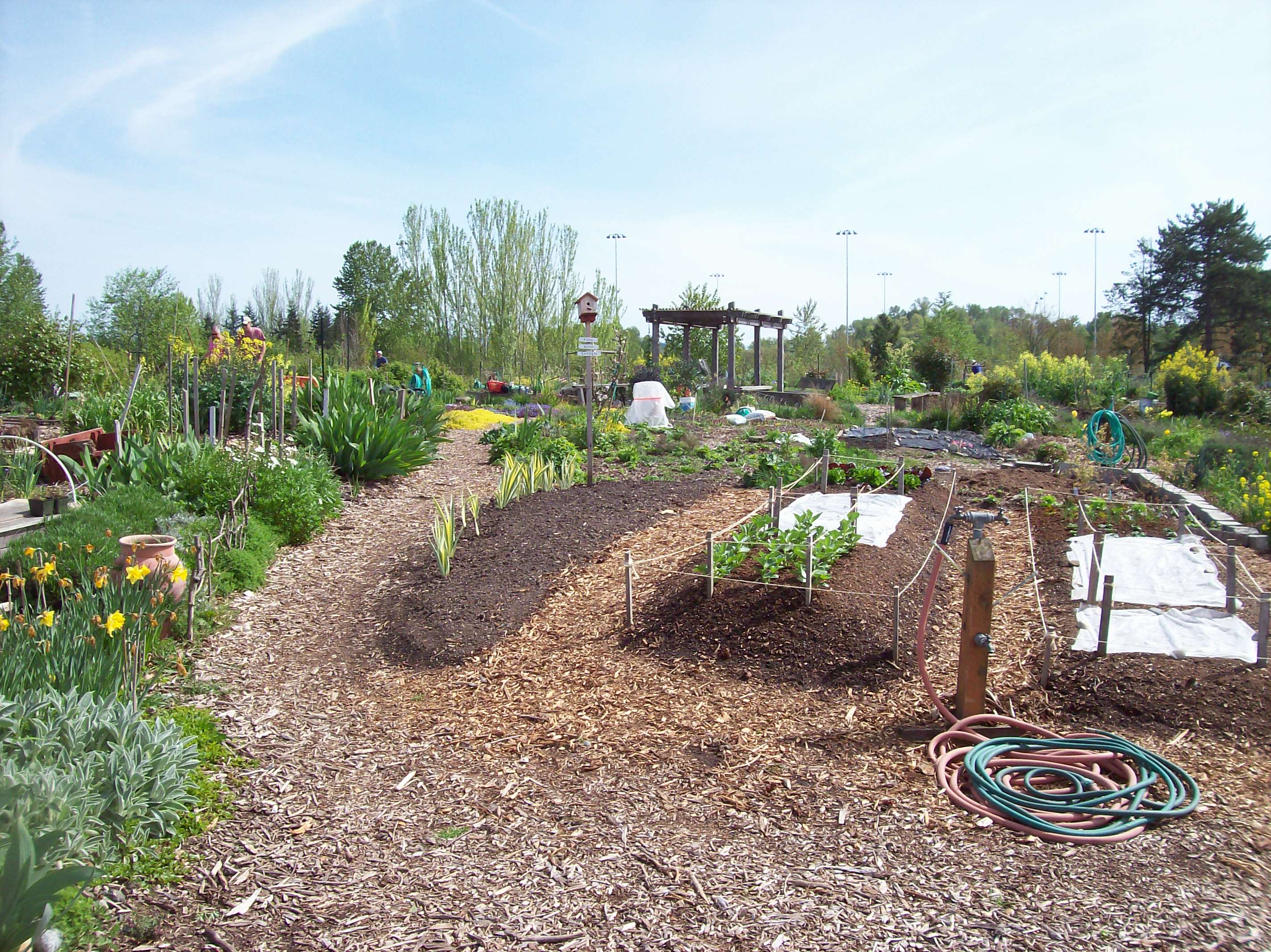
For example, here’s a bit of the humonguous community garden:

Then there’s the decaying industrial infrastructure next door:

Bizarre pieces of artwork that just happen to be laying around:

And then there are things that I’m not sure whether they are decaying industrial infrastructure or bizarre pieces of artwork (or both!):

As you walk around, you never know what you’ll find peeping out at you:

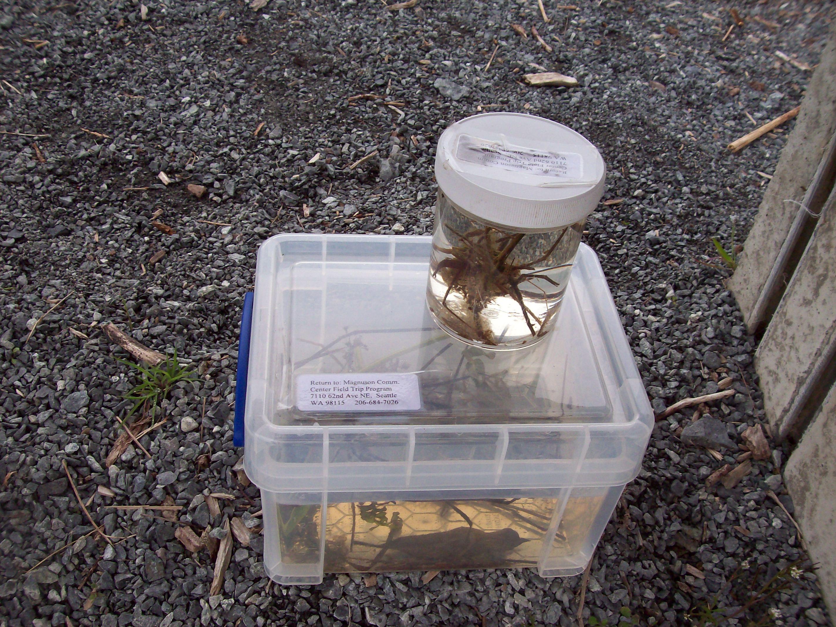
There are official science experiments for viewing (please do not touch!):

And I don’t know what to say about this, except that it’s interesting:

And surely not least, there’s ‘The Fin Project,’ which not-so-metaphorically cost billions of dollars and risked the fate of the planet in order to create:

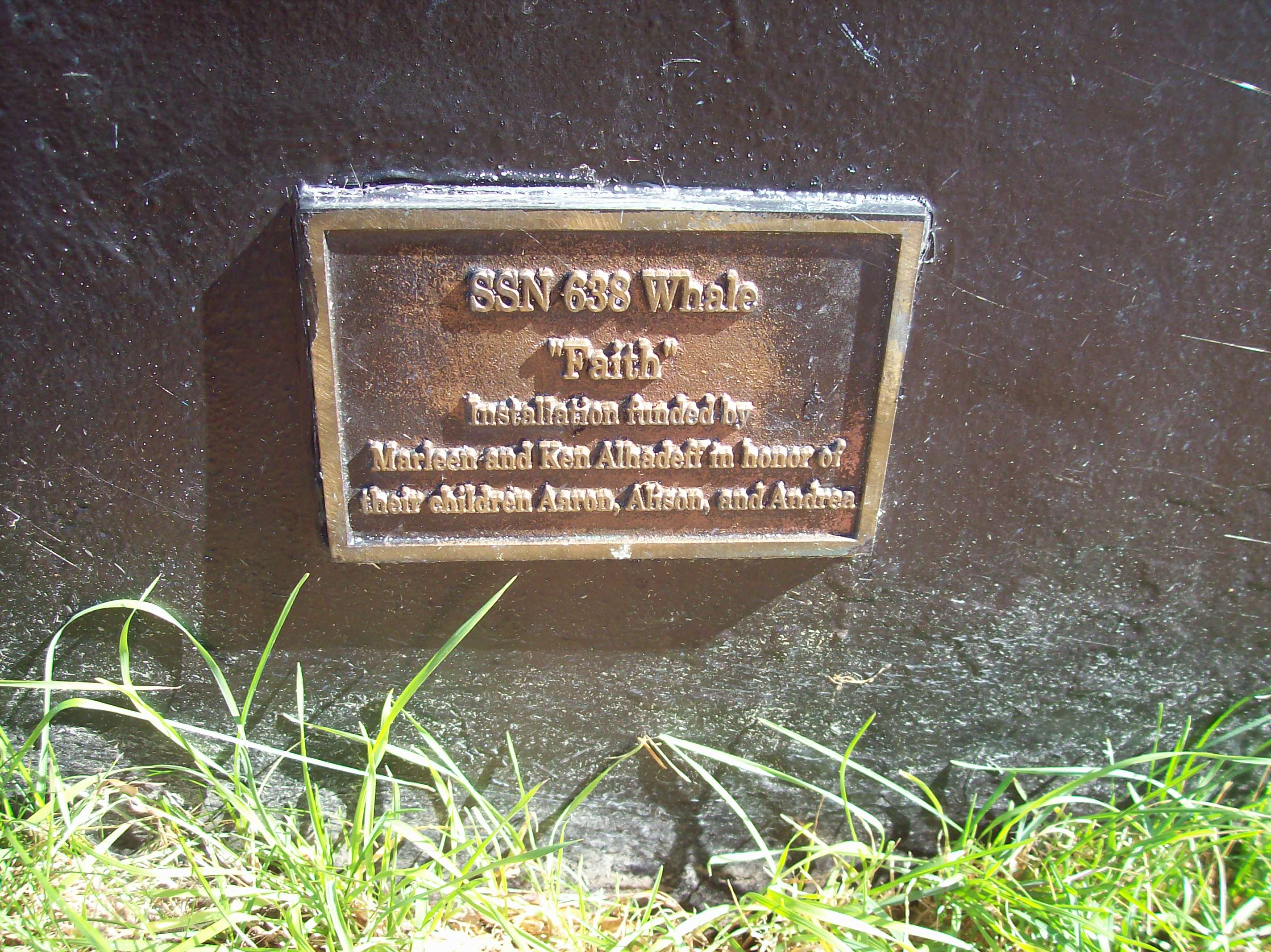
In case you’re still wondering, “What’s the big deal?” here’s one of the fin plaques:

The SSN on the plaque does not mean ‘Social Security Number.’ It’s the US Navy’s designation for fast-attack nuclear submarine. Yeah, these are real fins from real nuclear submarines. As public parks go, it doesn’t get much geekier than that.

Moving on, of course there’s Lake Washington, in case you want to have a picnic like people do in normal public parks:

Not shown: Kite Hill, the dog run, the oceanographic lab next door, the concrete bunkers, fields where you can fly RC aircraft (I think), the big climbing rock, and the vast realms of free parking.

In this era of Google Maps and automobile GPS, it’s not hard to find Magnuson Park. It’s about twenty minutes from Seattle downtown, and within bicycle distance of the University of Washington campus.

Given these pluses, Magnuson Park would make an excellent candidate for the location of a Seattle Maker Faire.

Posted in Uncategorized | Tagged , , , , | 2 Comments

Servo Command!

“Servo Command!” is a computer program written in the Processing computer language to control a continuous rotation servo via an Arduino interface.

I got a lot of the information out of books on Processing and the Arduino, then modified it to make this user interface.

The jumpers don’t match the servo colors because the jumper wire kit didn’t have the right colors in the right sizes.

The servo will continue turning on the Stop command unless an adjustment is made with the potentiometer. That’s inside the little hole on the top. You’ll need a small four-ply screwdriver.

I used the 11 pin on the Arduino for no reason other than it’s a PWM pin.

Here are the source codes for the Arduino and Processing programs. Note that 90 is stop and 0 and 180 are full speed. I chose half-speed but it would be easy enough to modify for full speed by replacing 45 with 0 and 135 with 180.

Arduino program “servo_test”:

// servo stuff
#include <Servo.h>
Servo myservo;
int pos = 0;
int angle = 0;

// serial stuff
int incomingByte = 0;	// for incoming serial 

void setup(){
  Serial.begin(9600);	// opens serial port, sets data rate to 9600 bps
  myservo.attach(11);
  myservo.write(90);  
}

void loop()
{
  
	// act on data only when you receive data:
	if (Serial.available() < 1) {
          return;
          }
          
	// read the incoming byte:
	incomingByte = Serial.read();

        // operate the servo
	if (incomingByte == 65){      // forward
            myservo.write(45);
          }   
	if (incomingByte == 66){      // stop
            myservo.write(90);
          }             
	if (incomingByte == 67){      // backward
            myservo.write(135);
          }    
  }

Here’s the Processing program “servo_command”:

// servo_command

// uses serial connection to tell servo what to do

import processing.serial.*;

Serial myPort;  // Create object from Serial class
int val;        // Data sent to the serial port

  
int clickflag = 0;
    
void setup() {
  size(480, 500);
  smooth(); 
  background(0);  
  
  String portName = Serial.list()[0];
  myPort = new Serial(this, portName, 9600);
  
  stroke(255);
  noFill();  
  rect(100, 100, 50, 50);
  rect(100,200, 50,50); 
  rect(100,300,50,50);
  
  fill(255);
  textSize(20);
  text("SERVO COMMAND!",100,50);
  textSize(14);
  int x = 160;
  text("FORWARD",x,125);
  text("STOP",x,225); 
  text("REVERSE",x,325);
}

void draw() {

if (mousePressed) {
     clickflag = clickflag + 1;
}
     
if (clickflag == 1){
     // check mouse range
     if ((mouseX > 100) && (mouseX < 150)){
          // forward
          if ((mouseY > 100) && (mouseY < 150)){
               myPort.write(65);
                 fill(0);  
                 rect(100, 100, 50, 50);
                 rect(100,200, 50,50); 
                 rect(100,300,50,50);
                 fill(255);
                 rect(100, 100, 50, 50);                 
          }
          // stop
          if ((mouseY > 200) && (mouseY < 250)){
                 myPort.write(66); 
                 fill(0);  
                 rect(100, 100, 50, 50);
                 rect(100,200, 50,50); 
                 rect(100,300,50,50);
                 fill(255);
                 rect(100, 200, 50, 50);                
          } 
          // reverse
          if ((mouseY > 300) && (mouseY < 350)){
               myPort.write(67); 
                 fill(0);  
                 rect(100, 100, 50, 50);
                 rect(100,200, 50,50); 
                 rect(100,300,50,50);
                 fill(255);
                 rect(100, 300, 50, 50);                
          }         
     }    
     
} 
}

void mouseReleased(){
     clickflag = 0;
}


Posted in Uncategorized | Tagged , , , , | Leave a comment

GIRC: Graphical Interface for Remote Control

GIRC is my program to operate a remote-control vehicle via computer with a graphical user interface. The program is written in Processing and an Arduino is used for the hardware interface.

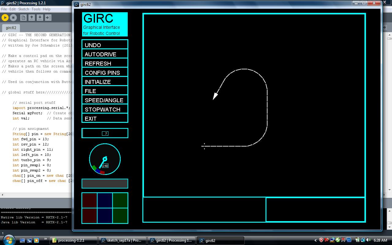
Here’s a screen capture with the path being drawn by clicking on the squares of the virtual keypad in the lower left corner:

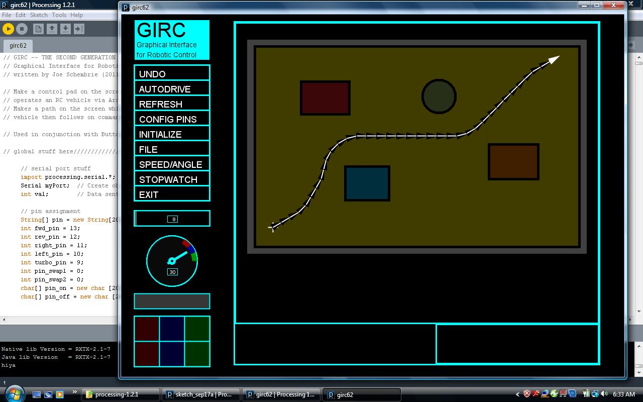
Once drawn, paths can be saved to files and replayed. Map images can be loaded, so that paths can be traced over them, like so:

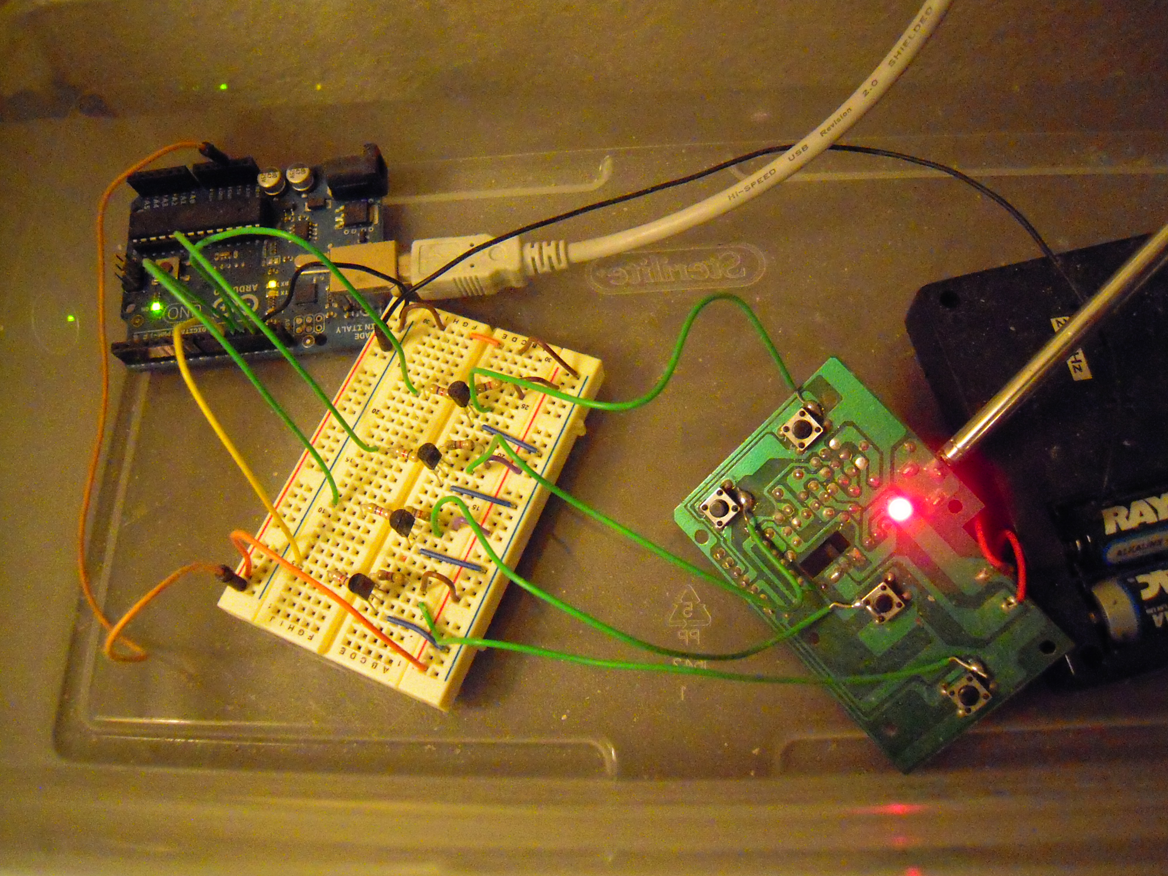
Here’s the hardware interface with the USB cable going to the computer and the actual RC keypad ‘hacked’ by simply soldering connections next to the control buttons:

Here’s a video of how the system works:

I also have videos of its operation on the floor, but suffice to say, the accuracy for a toy like this isn’t very good. I’m planning to buy an Arduino-compatible robotics platform and see what I can do with that.

Posted in Uncategorized | Tagged , , , , , , | 1 Comment

Elenco Amerikit Learn to Solder Kit Review

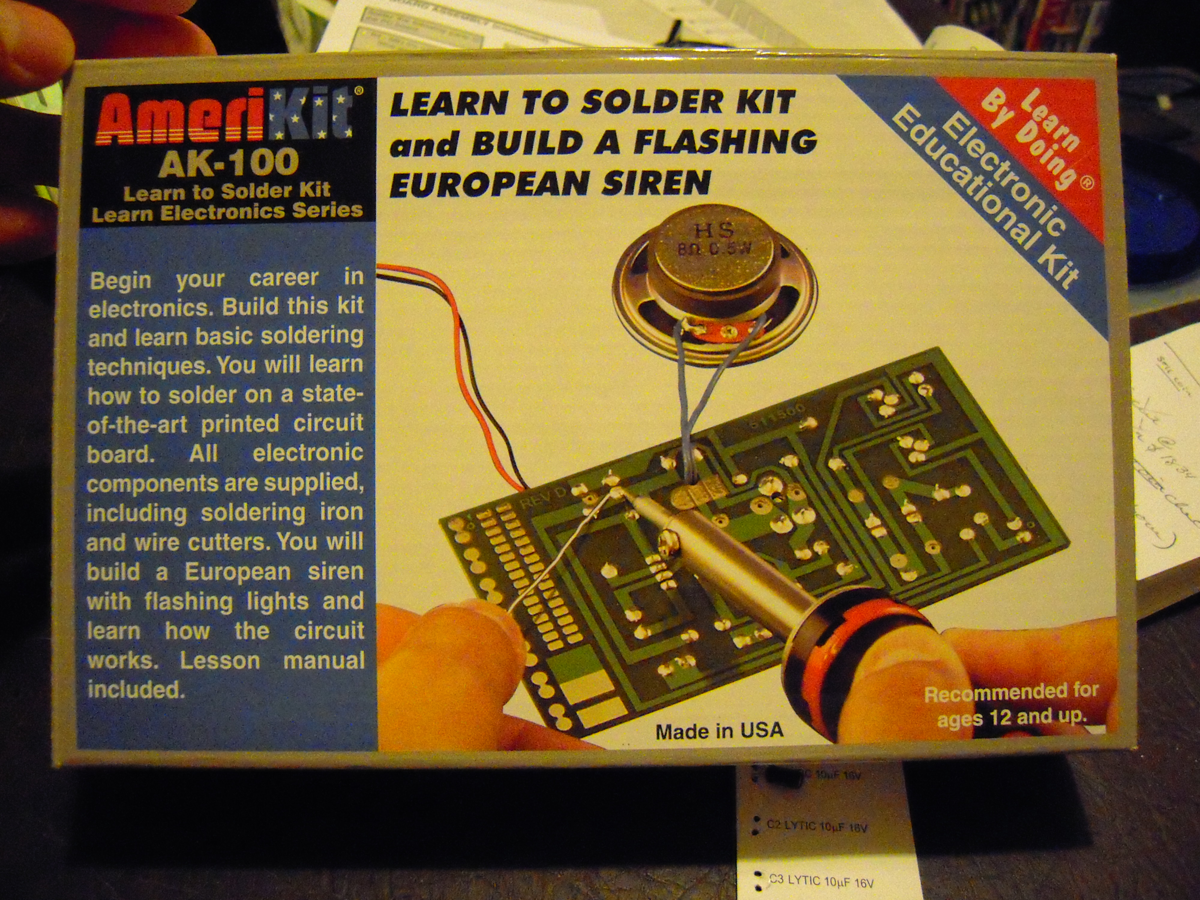
I got this kit because I wanted to brush up on my soldering skills.

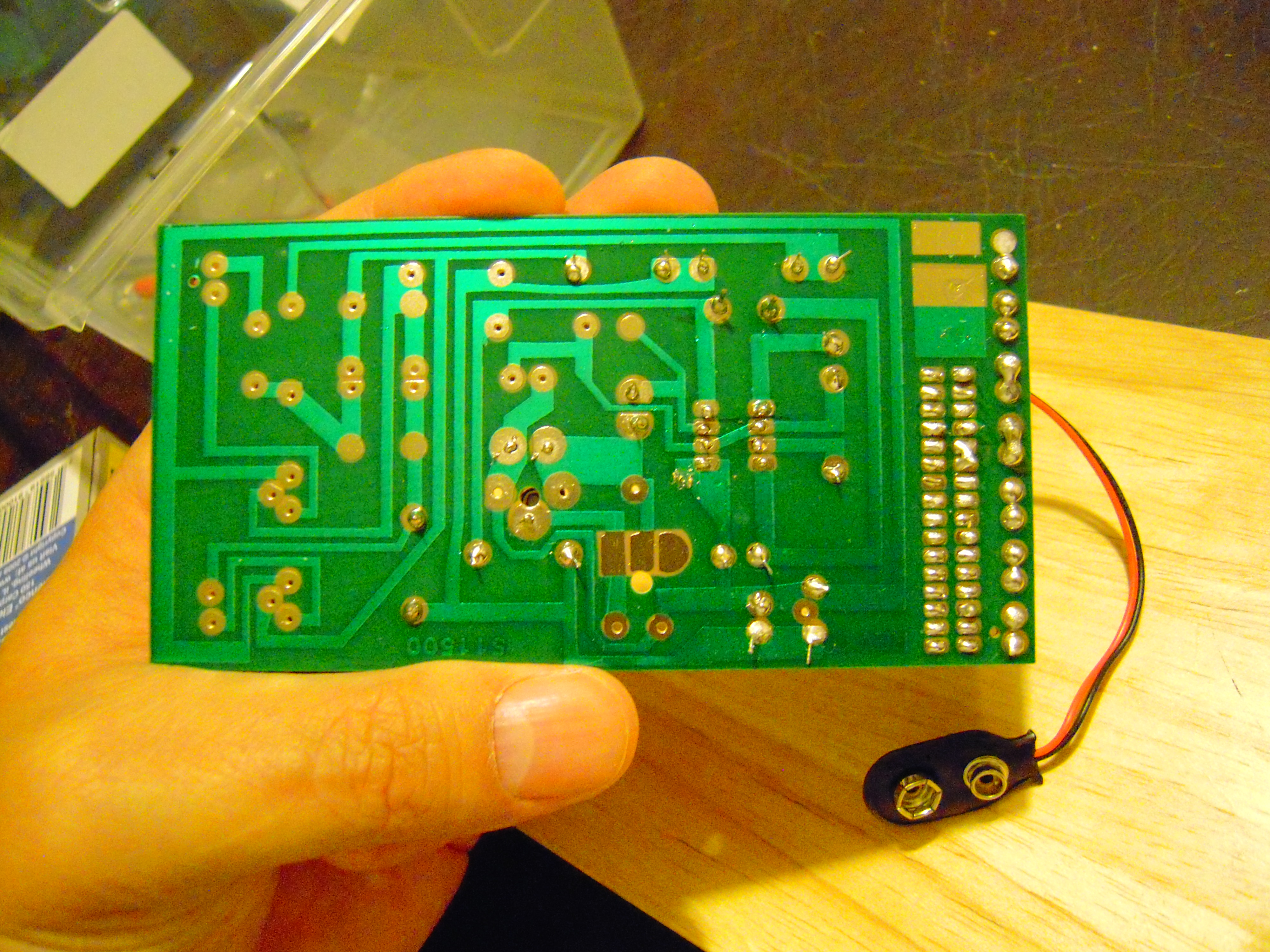
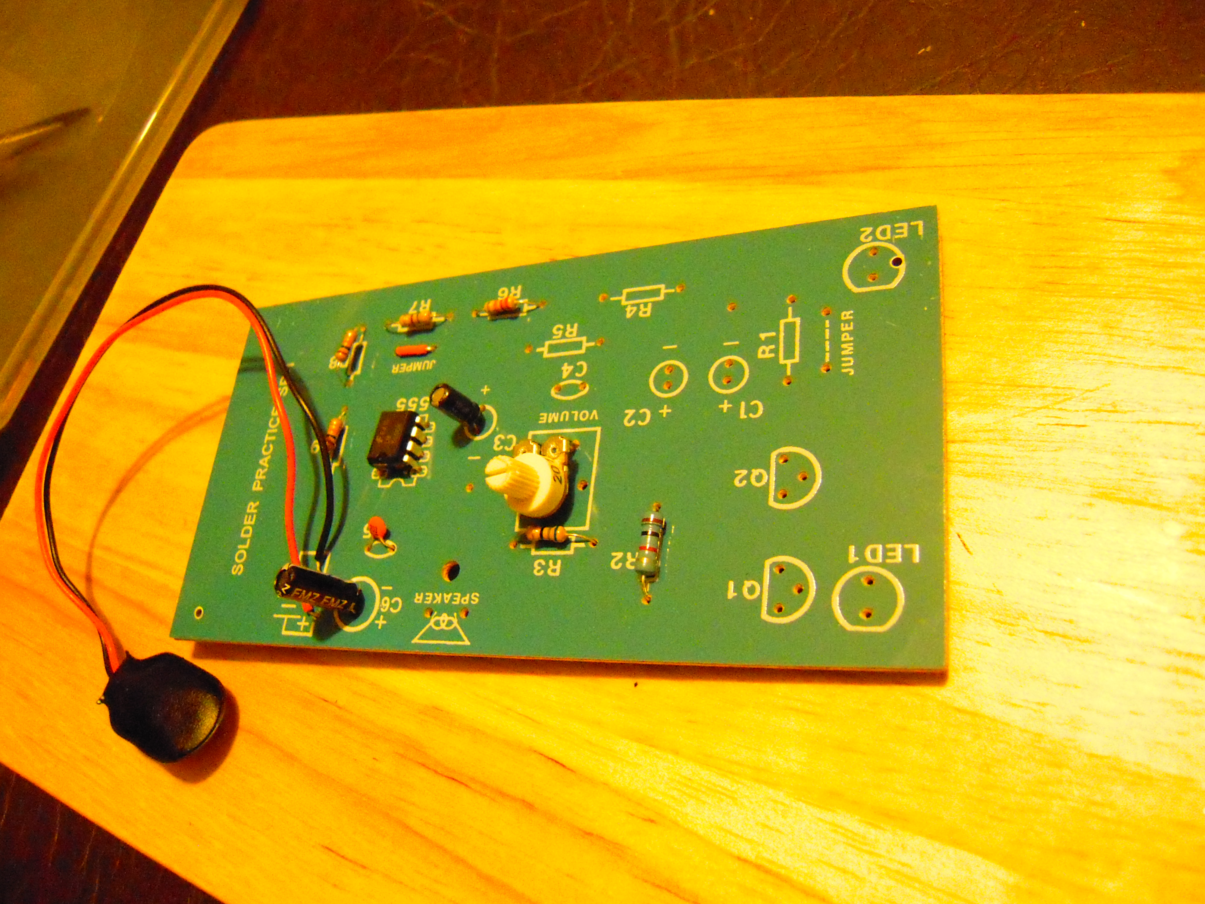
This is when I was about a third complete with the project. The rows of dots on the right are for practicing soldering before you actually begin to solder components.

The components are nicely labeled and attached to a card.

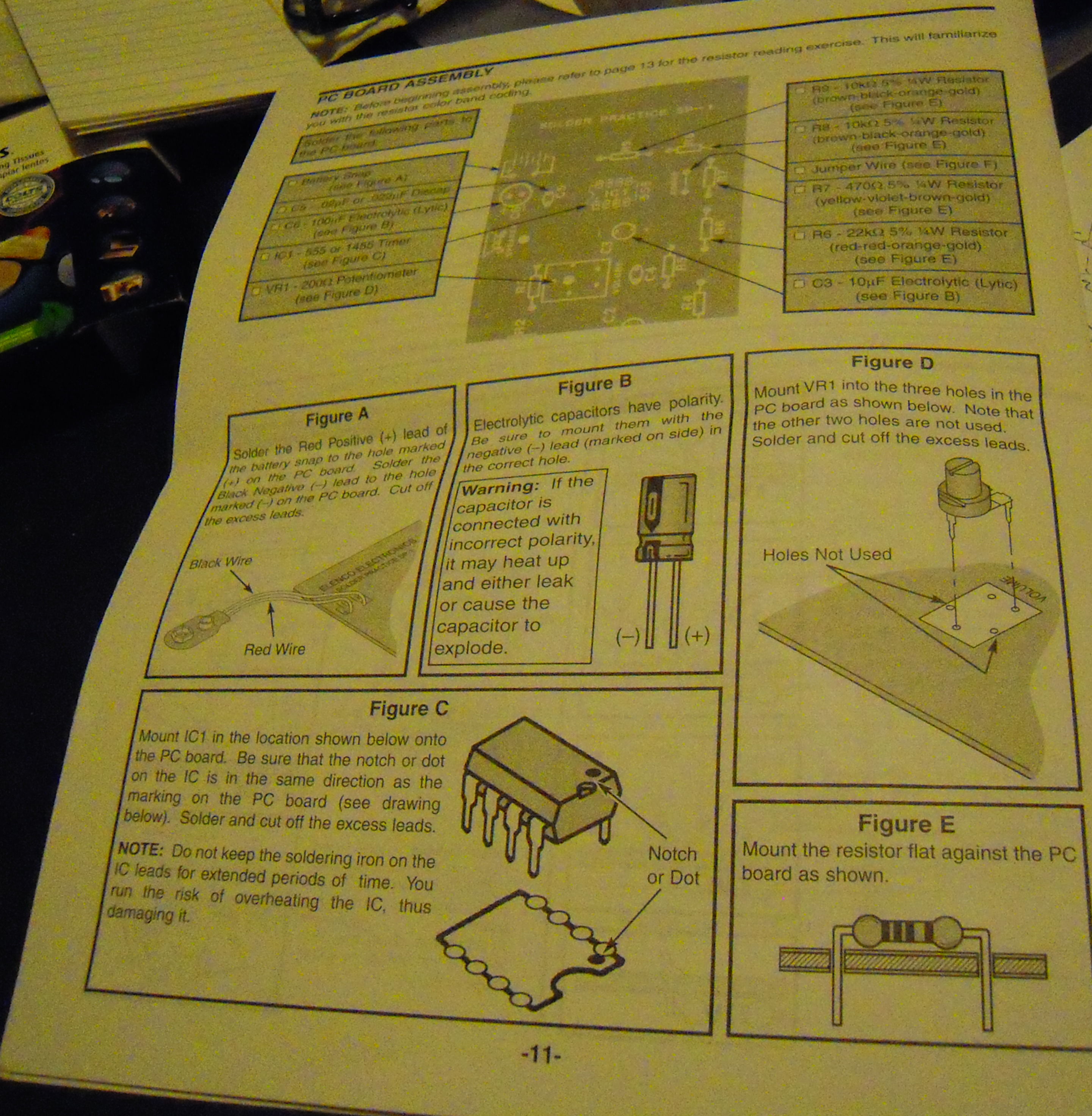
The booklet has very complete instructions.

The layout is illustrated on the top of the board so there’s never any doubt as to where to insert the components. Just remember to put the electrolytic capacitors in the right way! (Reading the board right side up is optional, but probably a good idea.)

If there’s one seeming flaw with the board, it’s that some holes are so close together that it was difficult to solder without ‘bridging’ across the circuit. But that turned out to not be a problem, and anyhow, it stretched my soldering skills to work in tight areas.

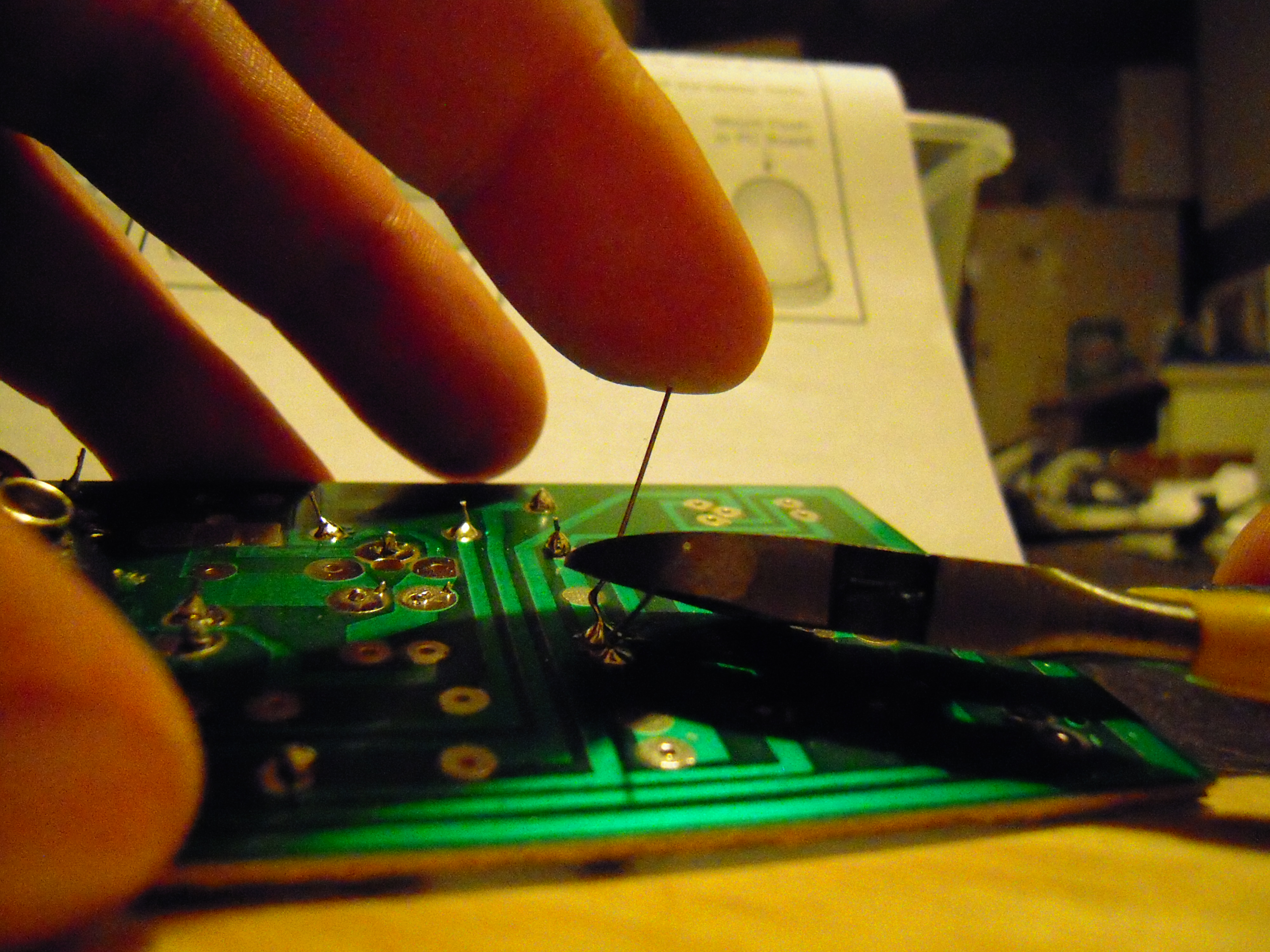
One tip I learned is that when clipping the component leads, lightly place a finger at the end. Otherwise, the clipped lead will go flying. One more reason to wear safety goggles!

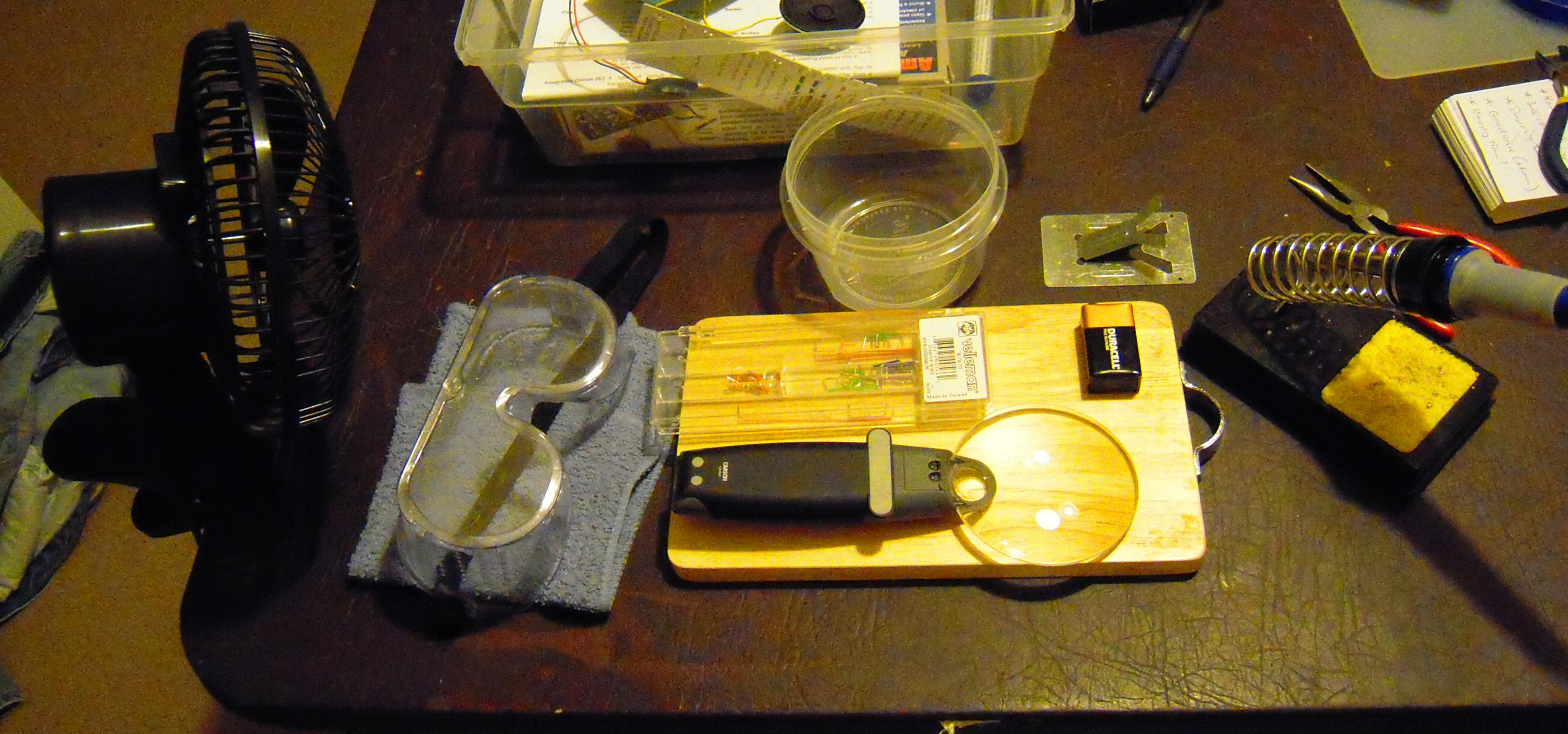
Speaking of stuff you either need or want that doesn’t come with the kit:

— a fan to blow away the solder smoke (better to get a smaller fan than the one shown here, or place the fan farther away).

— safety goggles (safety glasses may look cooler but aren’t enough!).

— a small towel (used as a ‘foundation’ to keep the board from rocking while poking with the solder and the iron).

— something to keep a solder dripping from burning your table (this mini-chopping board cost $3 at Goodwill).

— a box of jumper wires (unless you REALLY enjoy trimming the insulation off wire ends!).

— a cup to put the debris in (e.g., the clipped leads).

— a magnifying glass.

— a nine volt battery (that’s what the siren runs on).

— a soldering iron holder (the one that came with the kit is just a plate of metal and is shown above the cutting board).

— plastic shoe box to keep stuff organized.

Maybe you’re asking, “Did it work?” Well, not that this is punishment for your lack of faith in my soldering abilities, but here’s thirty seconds of European Siren:

(Note, as there is no reward for watching the full video, you may want to skip to the halfway point which is when, in a dramatic plot twist, I adjust the potentiometer.)

Lots of other people have uploaded videos of this kit onto Youtube, so if you’re a eurosiren addict you’re in luck.

This kit really helped me overcome my ‘solderer’s block.’ I may get the AM/FM radio kit next, to help with my ‘multimeterer’s block.’

And here’s the Amazon link: Elenco Amerikit Learn to Solder Kit.

Posted in Uncategorized | Tagged , , , , | Leave a comment

Quake off Vancouver Island

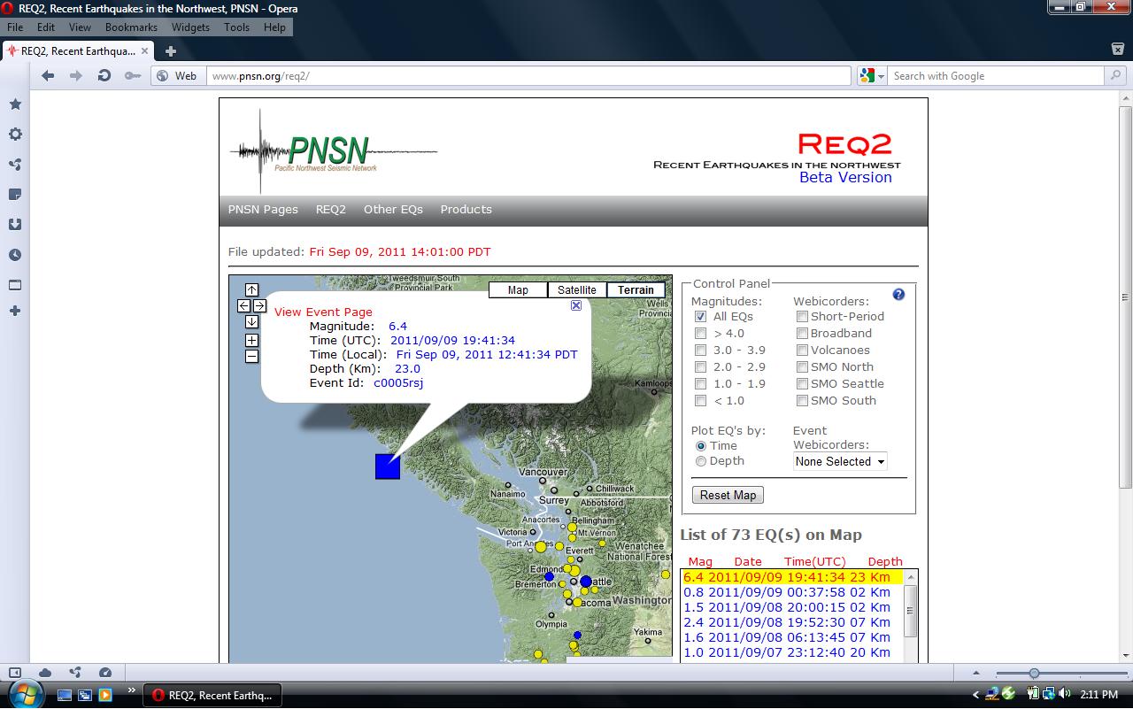
I live near Seattle and I didn’t feel this thing at all, but this has been an active year for earthquakes and so I like to keep track of these things.

BTW, the PNSN web page lists the number of quakes in the past two weeks, and 73 is high. When the number does get high, I start thinking, “Foreshocks.” And in this case, that was right.

Posted in Uncategorized | Tagged , | Leave a comment

Tomorrow’s Builders

Seen on a park sidewalk:

Posted in Uncategorized | Tagged , , , , , , | Leave a comment

Space Elevator Conference Robots

The 2011 Space Elevator Conference was held on August 13 in Redmond, Washington at the Microsoft Conference Center. I dropped by to take a few pictures of various types of robots that space elevator advocates hope might someday climb their ribbons in the sky. I wish I had taken notes, then I’d have captions, but anyhow here are the pictures:

This slideshow requires JavaScript.

Posted in Uncategorized | Tagged , , , | Leave a comment

Been a while since I’ve seen one of these

This is what a ‘calculator’ looked like when I was a kid. Only AFTER I had finished grade school did they come out with pocket calculators.

Back in the 80s, I attended an employee orientation session at Boeing. An engineer-instructor told the story of how back in the 1950s he had entered a room full of engineers working hand-crank calculators for a whole month to produce an airflow simulation graph. Then in the 80s, he entered a room and a gal was sitting at a supercomputer and pressed a key and the screen instantly generated the same kind of graph in multiple colors. He glared at her and she laughed.

Posted in Uncategorized | Tagged , | Leave a comment