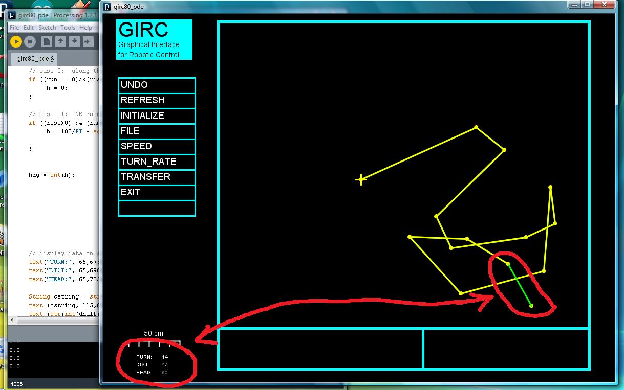
The user guides the robot in GIRC by creating a path. The path is composed of segments which are created by mouse clicks. The program calculates the length (or distance traveled) for the path segment and also the heading.
“Heading relative to what?” you ask, and that’s a good question. I assumed that the positive x-axis would be zero degrees and that the angle would increase going counterclockwise. Instead, it appears in the display that the angles are calculated going clockwise from the positive x-axis. I don’t know if that’s a property of Processing’s trig functions or if I did the formulas wrong. I’ll find out.
Anyhow, the distance looks right.
(NOTE: The TURN value is currently showing the segment number.)
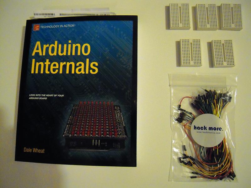
Videos of delivery guys gone wild may be viral these days, but Santa Zero was good to me and delivered these presents intact and on time. They will help in making my cheapbot kit a reality.
I’ve only just browsed the Arduino Internals book, but it looks like it contains a lot of useful information.
The mini breadboards come from Sparkfun for just $3.95 and conveniently are just the right size to fit between the headers of the Arduino. The Hacktronics flexible jumper wires cost about $10 what with shipping and handling added onto the price for a set of 100.
I’ve read that soldering requirements will cut sales of kits by 99%, so including a mini breadboard and jumpers for my robotics kit package is the way to go. Cheapbot is going to look different after this!
And so let us begin.
First, to review, here’s what the bot used to look like:
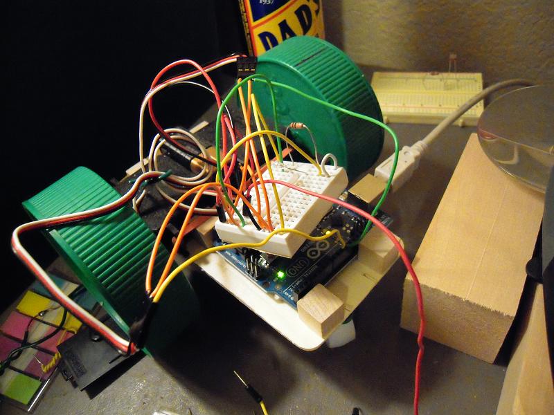
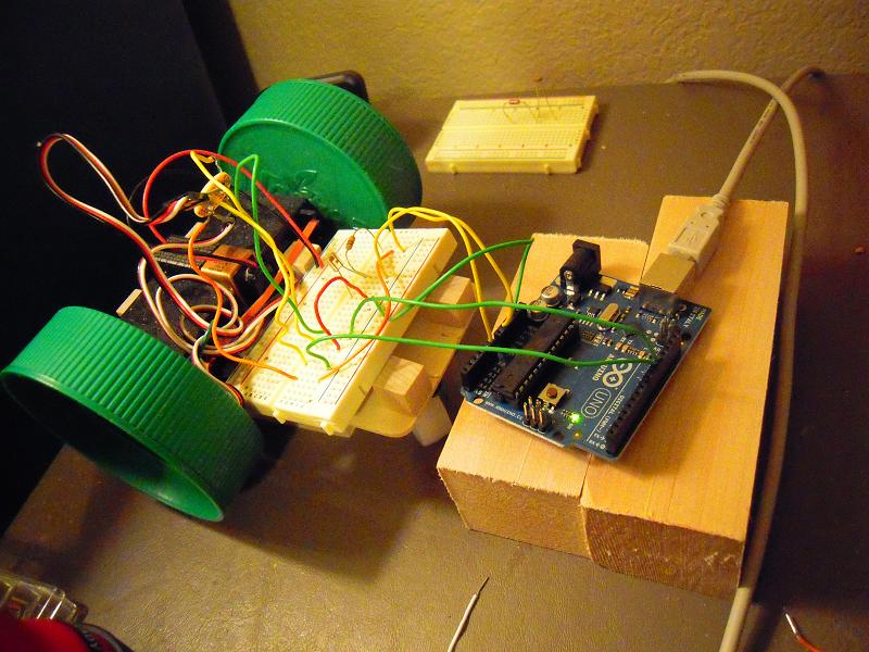
Note there wasn’t enough room to comfortably fit the breadboard and the arduino together on the robot chassis. But now . . .
I will have to make some kind of support-tray-holder for the breadboard, but for now this works fine.
And with a mini breadboard to join jumpers in a T, I no longer need this soldering kludge:
To think of all the time and trepidation I spent on dreading the task of soldering this thing! Well, now I don’t have to do any soldering for my kit, and as mentioned, 99% of potential buyers weren’t going to do it either.
BTW, I tilted the phototransistor back, and it made a HUGE difference in the responsiveness to the flashlight, as seen in this video:
(And another BTW: the loose red flexi-jumper that moves in the video is for the nine volt battery positive terminal to connect to the arduino Vin for running the robot independently on battery power. It will be connected when I run the robot on the floor, but by leaving it disconnected now I save on battery charge.)
GIRC (Graphical Interface for Robotic Control) is a program (aka sketch) that is written in Processing and enables the user to graphically program my robot to follow a course. The poor little microcontroller doesn’t understand computer graphics, so I have to translate the graphical information into numbers for each path segment: length of the segment, turn in degrees from the previous segment, and the heading (arbitrarily defined as the screen’s ‘up’).
These graphics-to-numbers conversion calculations will be accomplished in the seg_calc() function, which I’m working on now. At this point, however, I’m just trying to get the function to display information on the screen, as shown above. Once I finish that, I will be able to display calculation results onscreen and verify that they agree with the graphics, and so I can go on to write/test the calculations portion of the function.
(NOTE: if you click on the picture, it will magnify. And BTW, next time I’ll probably change LENG to DIST as it seems a more logical nomenclature.)
I have a program (aka ‘sketch’) which steers my arduino robot (ie, cheapbot) in a square path. I revised it to use a phototransistor as a mode switch between standby and act (ie, move) modes.
Originally, I used the delay() function for the timing of the servo movements, but that meant I was sampling the analog port that the phototransistor is connected to only once every few seconds. I’m reading Beginning Arduino Programming, and it suggested that instead of the delay function, use the millis() function in a while loop because then I could continuously sample the analog port inside the loop, many many times per second.
So that I did, and it kind of works. I think the reason that it doesn’t work as well as I’d like is because of the optical equivalent of mechanical switch bounce, but we’ll see what can be done about that.
One problem that I successfully trouble-shooted is that at first I was getting very strange, random responses from the robot whenever I shone the light on the phototransistor. I finally figured out it was because I was using an int type declaration for the time variable, and I needed to make it unsigned long. This is covered at the arduino site and also in the book.
Anyhow, this is what the behavior of the phototransistor as robot mode switch looks like so far:
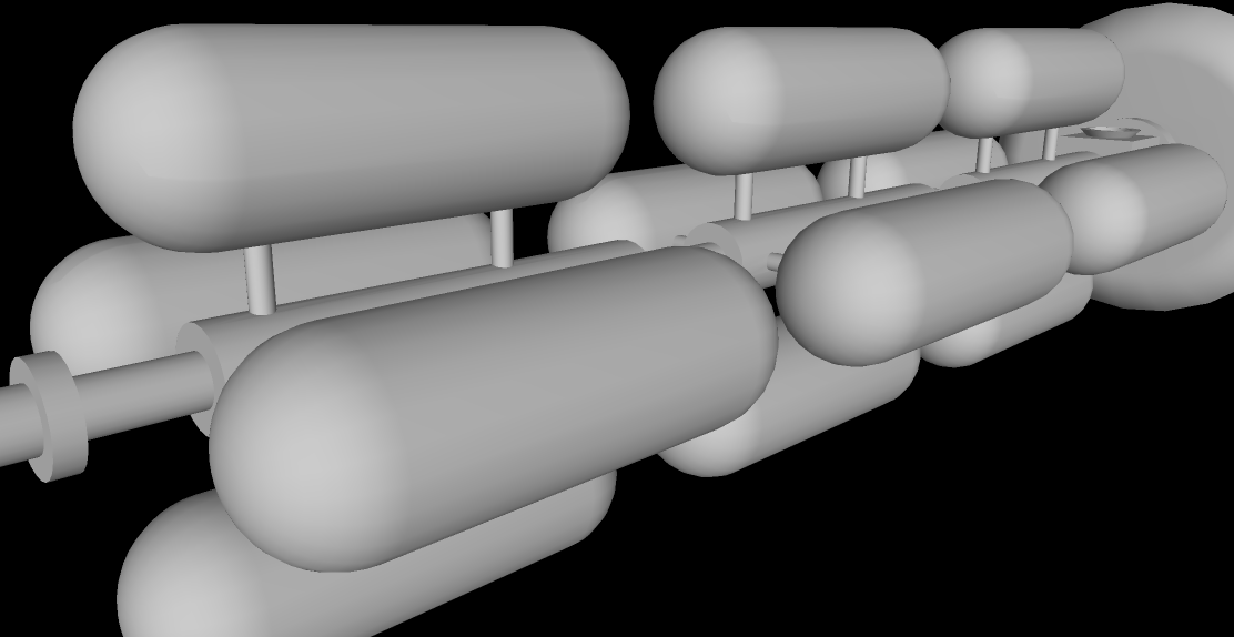
Starship Orinoco is a generation-type starship. It is fusion powered and has a cruise velocity of five to ten percent the speed of light. Hence it takes decades to travel to Alpha Centauri, the nearest star to our sun. The ship is two kilometers in length.
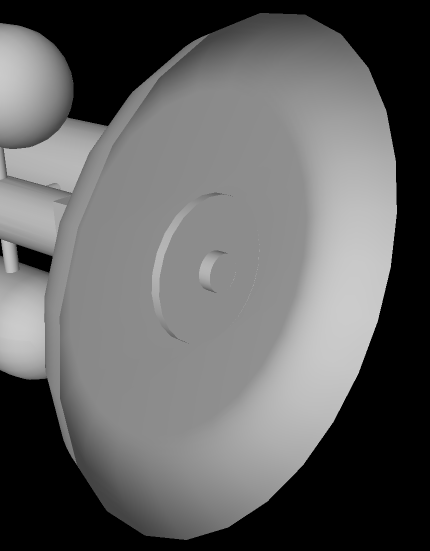
At the front of the ship is a radar to detect obstacles in the path of the ship so that they can be avoided. The hexagonal screen is charged to generate a powerful electromagnetic field around the ship to deflect the impact of micrometeorites. Side and rear radar are located at the tips of the projecting struts.
The service module contains hangers for shuttle craft used for travel between the starship when it is in orbit around the destination planet and the surface of the planet. There are also pod bays for probes, tugs, and various types of robots. Most of the module contains cargo and supplies for the colonists when they reach the destination planet.
The habitat wheel is where the passengers will while away the decades in transit between star systems. It rotates to provide one-third earth gravity and is three hundred meters in radius. With multiple levels, it provides over a million square meters living space for a thousand passengers.
Modular fuel tanks are filled with deuterium for the fusion reaction. The long boom between the passenger wheel and the engine is reminiscent of the spaceship Discovery in the movie, 2001: A Space Odyssey.
Four thrusters enable the starship to maneuver pitch and yaw for navigation purposes. The ship adjusts roll with an internal flywheel.
The engine has a ‘pusher-plate’ design reminiscent of Project Orion, in which deuterium pellets are launched behind the ship and fusion ignition is achieved with lasers and magnetic fields. Maximum acceleration is .01 g and it takes years to build up to cruise velocity.
Orinoco is pictured here traveling alone across the interstellar void but is likely to be part of a fleet of two or three other similar ships. It also has fleets of probes to venture millions of kilometers ahead of the ship’s path in order to detect and avoid obstacles such as asteroids and meteoroids.
Probably, such ships are the stuff of the twenty-second century, or beyond, but it’s fun to dream. And who knows, if medical science continues to extend human lifespan, people who are alive today might someday venture to the stars.
Here’s the thing about cheapbot: as soon as you program it, it wants to go. It really needs a mode switch with two modes: one to accept commands, and the other to execute them. Also I want to be able to make it stop without having to chase after it, pick it up, and pull out the battery high wire.
The idea of putting a phototransistor on cheapbot is that I can switch modes by merely shining a flashlight on the robot. In other words, I can attach the cable and download the commands, then place the robot on the floor, then shine a light on it and it’ll go. When I want it to stop, I just shine the light on it again, and en voila. No hassle of chasing after or pulling wires.
Shown in the photo is the breadboard setup, and once it fully works, I’ll solder stuff so that the robot can be mobile again.
Status on programming: yes, I can make the robot move when the light is on it and stop when the light is off, but what I want is to cycle modes when I shine a light. That is the next step.
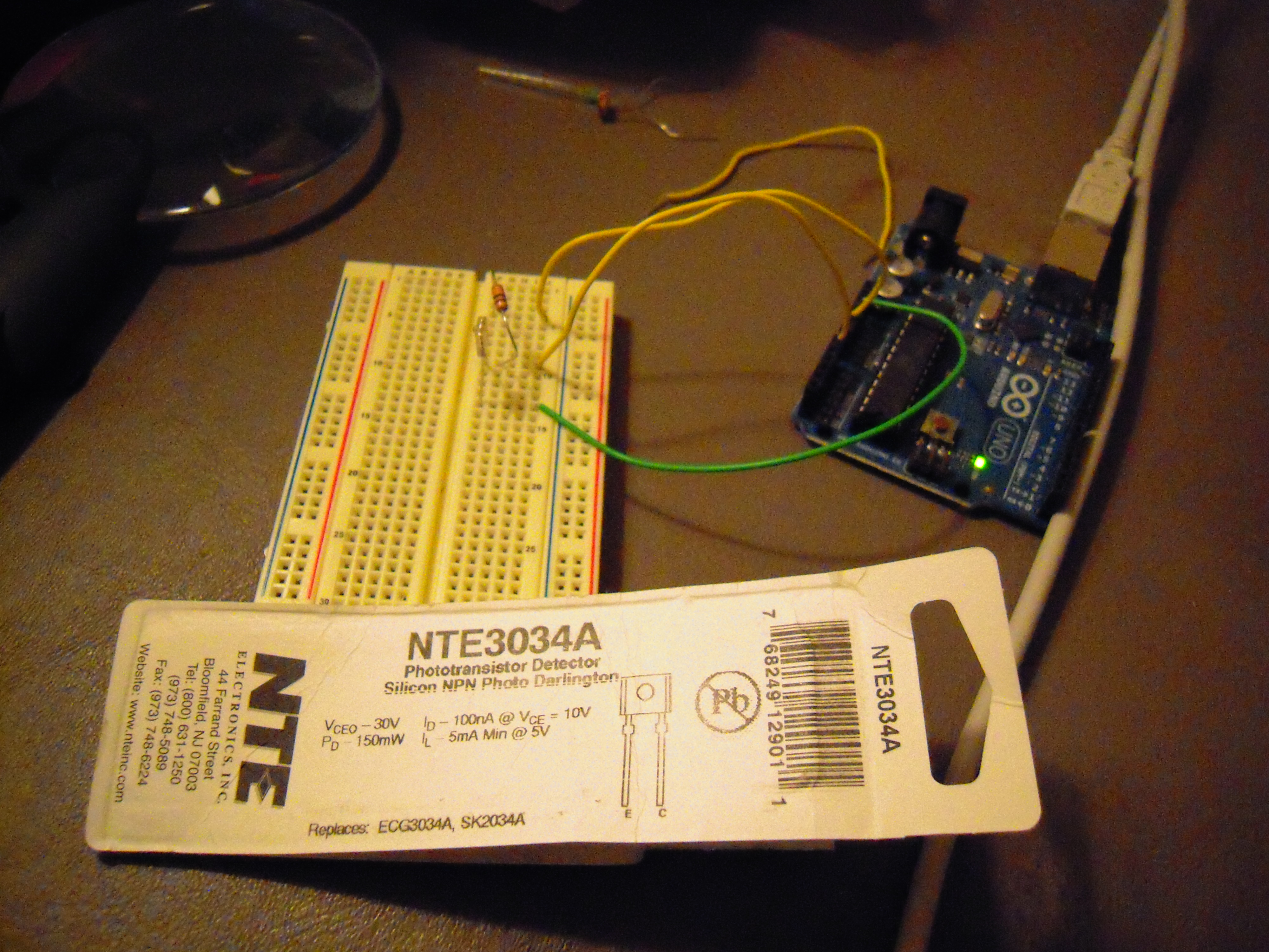
Here is the experiment with the photocell replaced with a phototransistor, the NTE3034A.
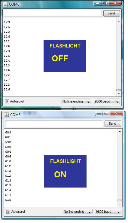
Here is the flashlight OFF data from the Arduino IDE serial monitor:
Here is the flashlight ON data:
This phototransistor is actually designed for infrared, so I was pleased that it responded to an ordinary flashlight, and as you can see, it had a more dramatic response than the photocell.
Another thing that I like about it is that according to its data sheet it has a switching speed of 60 microseconds, which means that it can receive signals at over 10K baud. That’s faster than the analog port read time for the Arduino, and more than fast enough for the application I have in mind.
This is an experiment out of the Getting Started with Arduino book. As you can see, an analog port is connected to a circuit with a photocell (Radio Shack part 276-1657) and resistor (220 ohm).
I used a flashlight to vary the light falling on the photoresistor, and used the Arduino IDE serial monitor to track the response at analog pin A0. (This is all covered in Getting Started with Arduino, Chapter Five: Advanced Input and Output.)
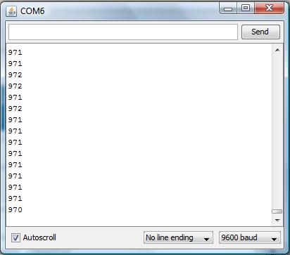
Here’s what the serial monitor reported:
(BTW, I originally used the 10K resistor recommended in the book, but the swing in output didn’t seem big enough for what I have in mind. I don’t think there’s a risk of burning out the Arduino or the photocell with a 220 ohm, but maybe I should check on that.)
This project actually relates to my budget robot, since I need a way of manually switching it between two modes. I figured that shining a light on a photoresistor was cooler than chasing the robot around and having to physically pull out a wire to make it stop.
This week I made progress on revising the Computer/Processing side of GIRC for my servo-driven budget robot, and now that I have a way to switch modes on the Arduino, I can start work on the Arduino/Wiring side of GIRC.
For Halloween, I thought I would try to make a glowing monster mask for my budget arduino robot. Here’s the original, somewhat overly ambitious plan that I made:
Since I already had the robot, the first thing I had to do was make the mask with Instamorph:
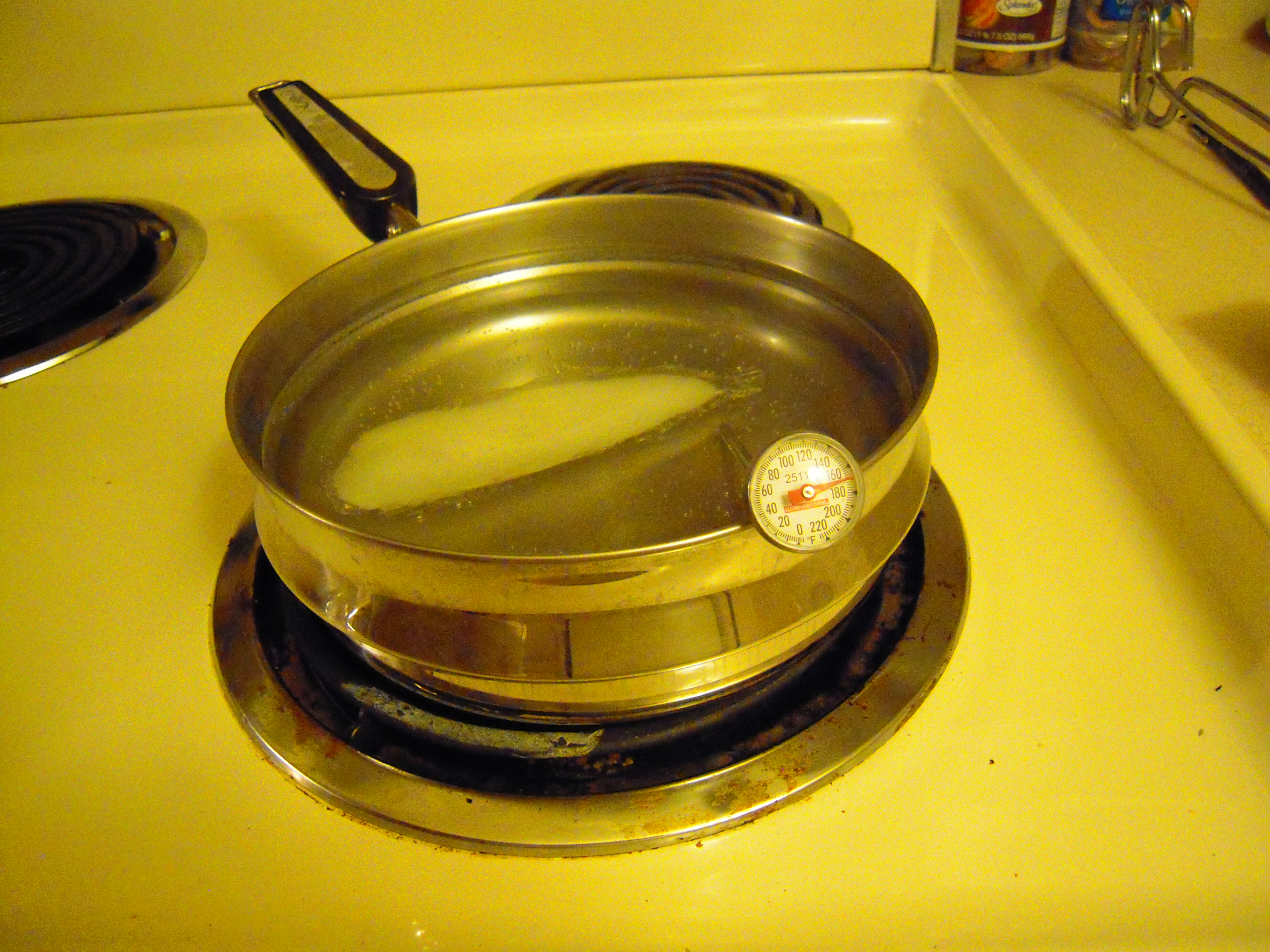
Instamorph goes into a pan of water heated to 140-150 F and when you take it out, it is moldable by hand. Here’s the stuff being heated (a little too high temp, I might add):
Here you can see that I’ve made the horns and am working on the eye holes:
Then I wrote a program (aka ‘sketch’) in Wiring (the Arduino computer language) for the ‘menacing’ path that the robot would follow. At the same time, I wanted the eyes to glow at varying levels, so I plugged the eye-LEDs into PWM pins. I mounted the robot on a block, uploaded the program and tested with the USB cable connected to my computer:
Once satisfied that they would work in breadboard form, I soldered the eye circuits with the help of ‘helping hands’:
(I’d pose the solder here too, but I had to hold the camera. Maybe I need another set of ‘helping hands!’)
Although I was concerned there wouldn’t be enough power from a single pin to power both LEDs, I did solder the ground wires together in order to use the single ground pin next to pin 13:
Hard to believe that couple months ago, I would have procastinated this project into oblivion rather than do any soldering. But compared to making the mask and debugging the program, soldering was a breeze!
Here’s a rear view of the installation of the eyes into the mask:
When placing the mask on the robot, I realized the mask was too wide, so I had to put it in warm water again and reform it. I was thinking I’d have to cut the sides, but it turned out that all I had to do was bend the edges. That was better anyhow, because it made the mask more three dimensional. Maybe I should have put a nose on the mask too, but I was anxious by then to move on.
Note the paper clips that are embedded into the mask here, and the jumper-wire fastenings:
Yes, it’s rather kludgey, but all of this is basically prototype work so I am forgiven.
Anyhow, here’s the video, courtesy of Youtube:
So there you have it — an Arduino Monster Robot. And despite my efforts on the mask, perhaps the scariest thing about this robot is all the spaghetti wiring. Well, the Arduino does come from Italy.
Maybe next Halloween I can build something bigger with, yes, a nose — but also maybe a face that glows an eerie yellow and sound effects that growl and roar when facing the viewer/victim. The Arduino Uno has extra pins for all kinds of ideas.