
Normally you don’t use an ATTiny85 to drive an RGB LED, because an RGB LED needs three pulse width modulation pins and the ATTiny85 only has two. However, for the application of a flickering candle, you need only two PWM pins, the red and the green, and for that the ATTiny85 does the job just fine.
Unfortunately, my smartphone camera doesn’t do the color and intensity changes justice, but here’s the video:
Here’s a photo of the setup in the video:
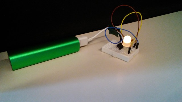
As you can see, the through-hole chip is puny compared to the LED.
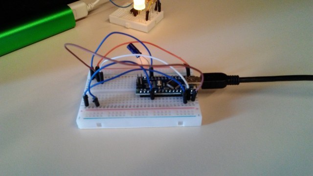
And here is an Arduino Nano pressed into service as an ATTiny85 programmer:
In case you’re familiar with using Arduino but unfamiliar with how to use an ATTiny85, Matt Richardson made a great video on the topic here:
To avoid the hassle of shuttling the ATTiny85 chip back and forth between the programmer and application breadboards, I recommend first testing your program (aka sketch) on your Arduino until it’s debugged, then moving the program from the Arduino to the ATTiny85 .
When converting a program from the Arduino to an ATTiny85, remember that you have to translate pin numbers. I made a conversion chart here for doing just that.
_________________________________________________________________________________
If you like reading science fiction and fantasy, you might enjoy my ebook trilogy beginning with The Wizard from Earth.

Have you snipped (manually cut it ) the other end of the USB Cable to give the +5V ?
Yes, I went to a dollar store (Daiso Japan) and got a USB phone charging cable for $1.50. I cut open the cable and soldered jumpers to the black and red wires so that it could be used with a breadboard.
In your earlier link you have used the PWM pins, however in this blog you are using the Digital pins ? Yes ?
PWM pins are a subset of digital pins. On the Arduino, the D0 and D1 pins are digital but not PWM. On the ATTiny85, D0 and D1 are digital and PWM.
For more information, see my blog post: https://engineerzero.blog/2013/05/07/attiny-4585-pin-conventions-for-arduino-ide-sketches/
Actually Attiny 85 has 3 PWM outputs. At least with this core: https://github.com/SpenceKonde/ATTinyCore
It seems to work fine.
Any chance you have posted the code somewhere?
Wow, it’s been a while. I found a function in my multimode flashlight sketch that I’ve adapted here for just the flickering candle. If you don’t want to use a potentiometer to vary the redness or greenness of your flame, you can experiment by plugging in constant values for potval over the range 0-1023 until you find something you like.
Good luck.
int red = 0; // the pwm pin attached to the red rgb lead.
int green = 1; // the pwm pin attached to the green rgb lead.
int potpin = 3; // an analog-readable pin attached to a potentiometer
void setup(){
// initialize the pin modes
pinMode(red, OUTPUT);
pinMode(green, OUTPUT);
pinMode(potval, INPUT);
// seed the random number generator
randomSeed(100);
}
void loop(){
// makes a flickering candle light
int k = random(0,100);
int potval = analogRead(potpin);
float p = float(potval)/1023;
int rmag = 255 – (15 + 155 * k/100)*p;
int gmag = 255 – (10 + 55 * k/100)*p;
analogWrite(red,rmag);
analogWrite(green,gmag);
int d = 50+300 * random(0,100)/300;
delay(d);
}
Thanks! Collecting a few methodologies, and yours looked most interesting.