
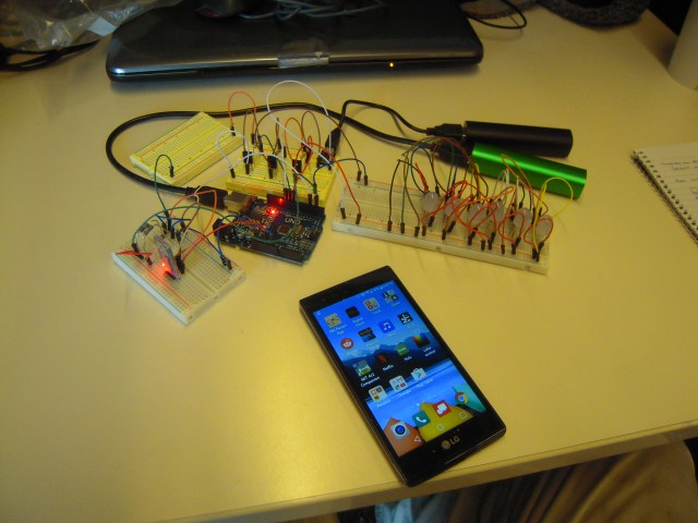
Many people have done projects similar to this where they use their smartphone to control an RGB LED. My project has some twists. First, I traded color variation for intensity variation. Second, I routed the Arduino PWM signal pins through power transistors so that I could drive multiple LEDs. Third (for now), I’m using phone charger battery packs so that eventually this thing can be mobile.
Here’s a video, I apologize for the quality, but it’s short and gets across the idea:
Here are some photos of the apparatus in close up. We’ll start with my smartphone, an LG K8V, as ordinary as they come:
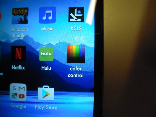
The app is called ‘color control’ for the current icon. I used app inventor to create it, and also referenced a lot of online examples. App Inventor is a great resource that makes programming apps easy, and it’s great that so many people are willing to share their code! I have some tweaks to my code, which I’ll get around to sharing once it’s stable and if anyone is interested.
And here is what the app screen looks like:
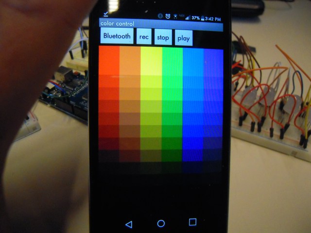
Connecting to Bluetooth is simply a matter of touching the button, then selecting the Bluetooth device from a list. Oh, and remember to turn on your phone’s Bluetooth!
Here’s the Bluetooth hardware set-up:
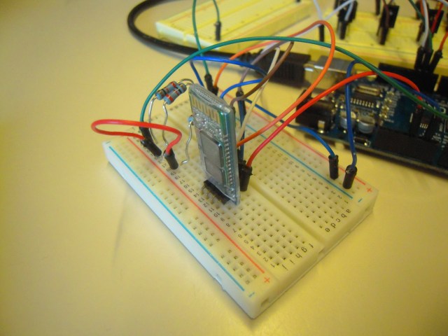
The Bluetooth device is an HC-06. Note the resistors, the receive pin can only take 3.3 volts while the Arduino is sending 5 volts, meaning that you have to use a resistor bridge.
You all recognize the Arduino:
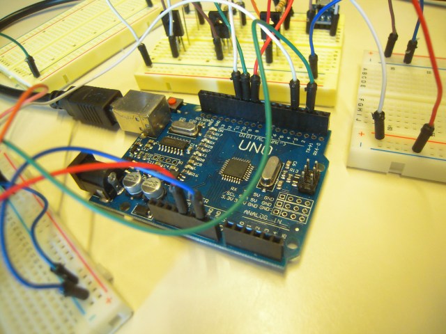
I’m using an Uno R3 here, but I’m planning to go to a Nano, which is smaller and less expensive and, I hope, less at risk of instability when supplied power is limited to five volts. We shall see . . . .
Here are the power transistors:
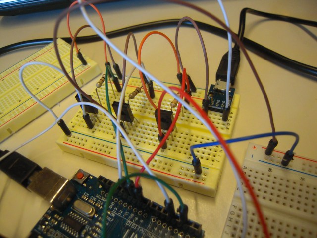
They are BD139s, NPNs that allow 1.5 amps through the collector-emitter path, or enough to power 25 RGB LEDs. The Arduino pins by themselves could only power one LED, while ordinary transistors would only power three or so. Power transistors are cheap, so no big deal.
The green patch in the upper right hand corner of the breadboard is the USB power breakout. A very handy thing to have, I wish I’d known about them when I was working on Project Grisbot (my robot) many years ago, I could have used phone charger battery packs in lieu of 9 volt batteries back then.
And here are the RGB LEDs:
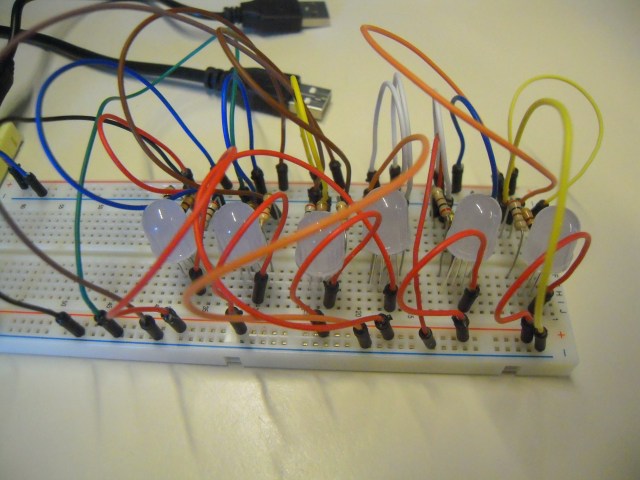
I used common-anode RGB LEDs because I wanted the transistor at the ‘bottom’ of the circuit branch. Thus current pours in from the battery pack into the LED, then branches into the resistors, and then the resistor branches of red, green, and blue respectively combine to enter the collector node of the respective transistor, where the signals are modulated by the Arduino at the base.
BTW, all the resistors here are 200 ohm. I calculated that to keep the current through the LEDs down to 20 ma.
Anyhow, that’s the project as it stands. The goal is to make this prototype into something that is truly compact and mobile. Plans include using an Arduino Nano and a real circuit board. The big changes, though, will come in the programming as I intend to make it possible to save and replay files that are sync with music.
