The L9110 motor control chip doesn’t really do much controlling. It lets you operate the motor to spin in one of two directions. Of course, there are times when this is important. In the case of a robot motor arm motor, the chip allows the motor to raise and lower the arm.
Here’s a link to a 9110 data sheet.
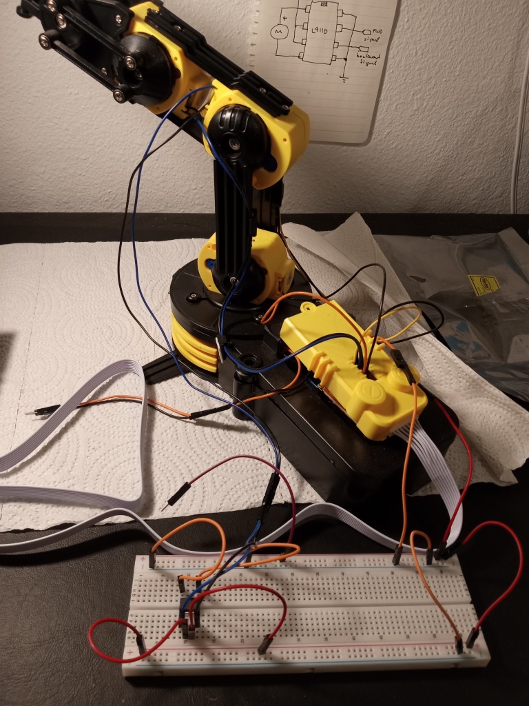
Here are pictures of an OWI-535 robot arm with one motor connected to an L9110. I had jumpers so I used those rather than cut wires.


The color coding helps. Red is positive power, orange is ground, the blue and the black connect to the motor, and the . . . purple . . . connects a voltage to the forward and reverse signal pins.
Here’s my hand connecting the powered purple jumper to the signal pins. The robot arm motor responds accordingly:
So why insert motor controller chips when the control pad that comes with the arm already has perfectly good switches? Well, I want a microcontroller to operate the arm, and in order to do that, I need the motor controller chips to interface between the microcontroller and the arm.
(Spoiler alert: the microcontroller will be an arduino.)
