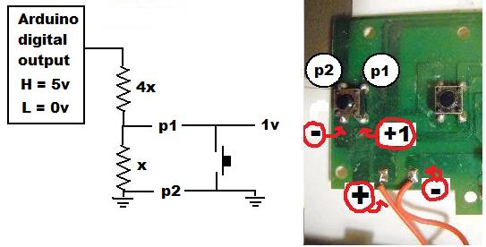
The Neph came over and we probed the RC circuit with the analog multimeter that I purchased from Radio Shack. I was astonished to find that the voltage on the high side of the push button wasn’t even a single volt. Actually it’s so low that a diode across p1 and p2 won’t even light up.
I’ve come up with the idea shown for an Arduino/RC board interface circuit. The resistor values (TBD) are such that one is four times greater than the other. Then, when the Arduino digital output (pin TBD) goes high, it generates 1 volt at p2. Counterintuitively, that is the equivalent of the button being unpushed.
To simulate the button being pushed, the Arduino digital output has to go to low — ie, ground. The RC circuit is operating on two AA batteries, so I’m pretty sure the current won’t burn out the Arduino. Indeed, other way around, I should choose resistor values so that the Arduino doesn’t burn out the RC circuit. Next time.
It also occurs to me that while transistors switches probably won’t work here because of the low voltage, a mechanical relay could. So I should look for some relays on the Internet too.
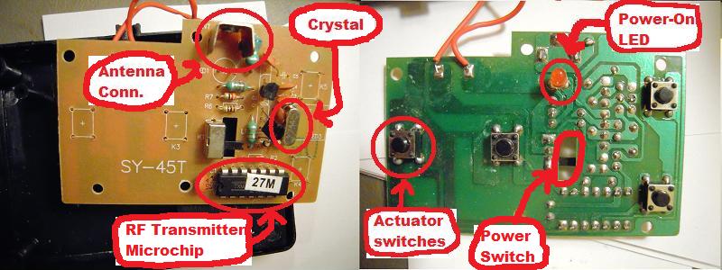
Here are photos of a RC toy vehicle’s remote control pad circuitry exposed. I reversed the back side so that the points would correlate with the components on the front.
The chip identifier number under the sticker is unreadable, which is unfortunate since the chip is the most interesting thing on the board by far.
Anyhow, the plan is to connect this to the Arduino so that I can control it from my computer with a variation of the LED-color switching program that I wrote.
By the way, I think I should mention that I am an utter newbie when it comes to programming in Processing, but there is so much stuff online to copy and paste that it was really quite easy to get up to speed.
Also BTW, the big digital multimeter with PC interface that I bought a couple years ago and never took out of the box only gives me a backwards 7 for display. Anyway, it cost more than the Arduino, so it was open to question whether it made financial sense to risk connecting it to the RC circuit in lieu of just connecting the Arduino without testing first. So I bought a cheap analog multimeter, which I will use on the circuit when my nephew comes over again tonight.
Tired of coming up with random computer passwords, then having to remember them and/or find a place to hide them when you write them down? How would you like to be able to keep your computer passwords written in plain sight — but no one but you can read them?
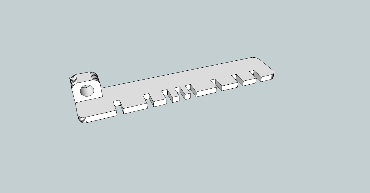
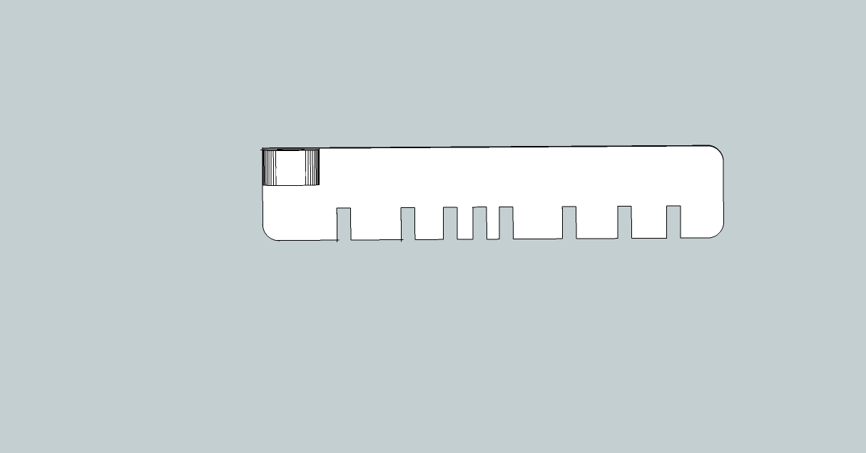
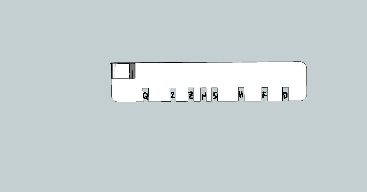
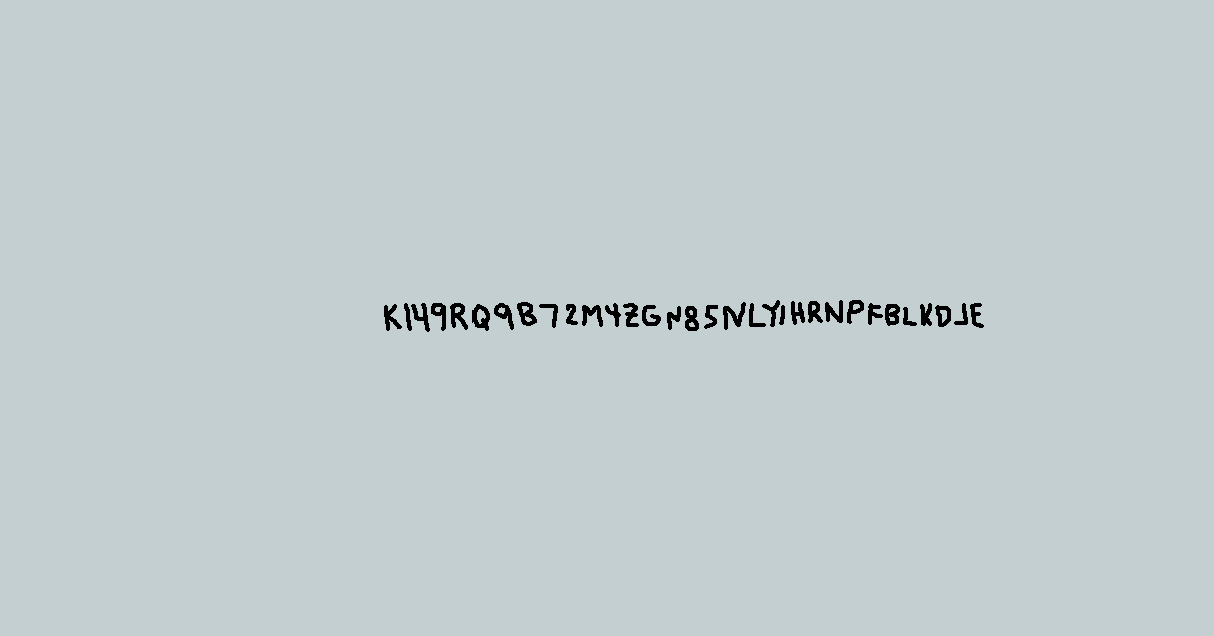
This is an idea I came up with a while back. The idea is to place it flat against a sheet of paper and write a computer password in the slots. Then remove the key chain and fill in the spaces between the password letters.
The result isn’t unbreakable, but a would-be codebreaker would need to try millions of combinations to figure out the password without the help of the key.
In action, it works like this:
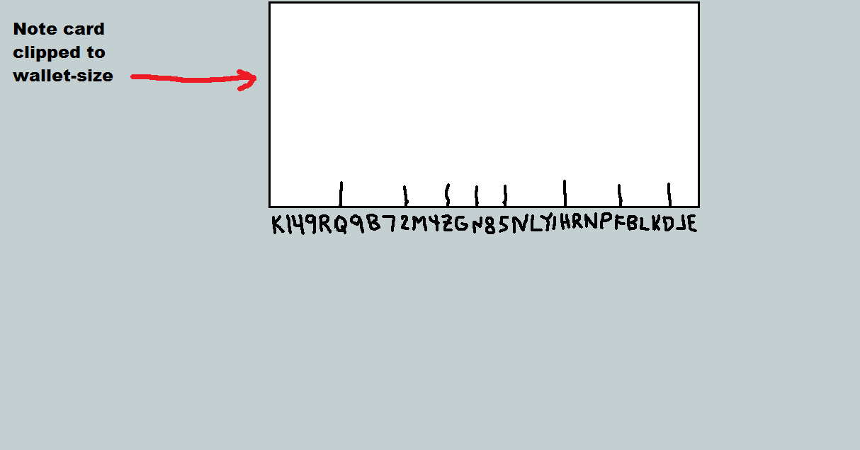
Originally, I intended this to be 3D printed for the Makerbot, which still sounds like a fun idea, but then I realized that all you really need is to cut a 3×5 notecard down to wallet size and write (scrawl?) ‘tick’ marks along the lower edge, so that it would work like so:
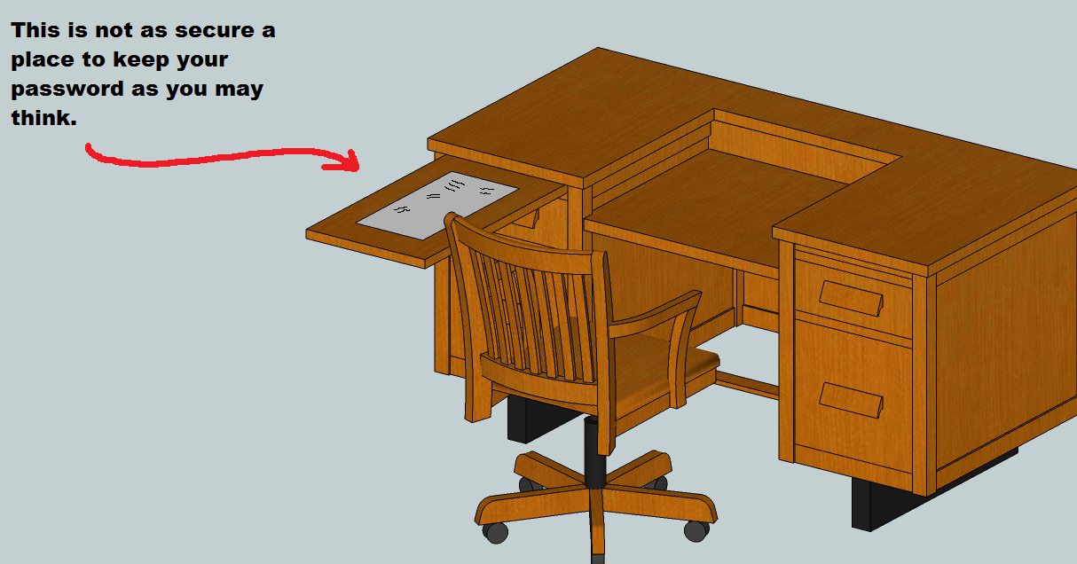
Of course, if someone finds your password key chain and/or card, they can read all your passwords. But when I was working in a corporate office, a lot of people kept their passwords openly written on sheets of paper taped to those little slider tables that pull out from desks.
Or they used 123456789 for a password. That’s ineffective too.
I viewed a video on Youtube of a ‘battery switch’ station, and the facility looked like it cost a couple million dollars. That didn’t seem very practical. If you want this idea to take off, battery swap stations have to be much lower in cost.
The battery probably needs to be larger, and so correspondingly the robot. There should be support for the cradle when it extends, perhaps provided by another robot. Anyhow, a first attempt.
As I’ve mentioned in previous posts (like the slideshow here), I want to build a teleoperated mining robot. Since I’m somewhat short of both cash and experience, I have to start small.
One key part of the system will be to create an interface to control the robot via computer. And to do that, I have to first be able to control anything, anything at all, by computer.
Hence, the following project.
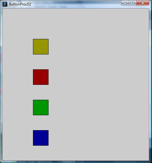
First I wrote a program — or ‘sketch’ as it is called — in the Processing computer language. Here’s what the sketch window looks like on the computer screen:
You take your mouse cursor and click on a square. The color of the square goes from dim to bright. At the same time, an LED of the same color lights up. Click the square again, and it goes dim and the LED goes off.
The whole circuit looks a little like this:
The laptop runs a Processing sketch, which produces the screen image of colored squares, which the user then clicks with the mouse. The Processing sketch reads the clicks and converts them into one byte commands which are then sent over the USB cable to the Arduino.
The Arduino has its own sketch which reads the commands from the USB cable and interprets them to turn the respective LEDs on and off.
Although the USB cable can send data back from the Arduino to the computer, I’m not using that capability here.
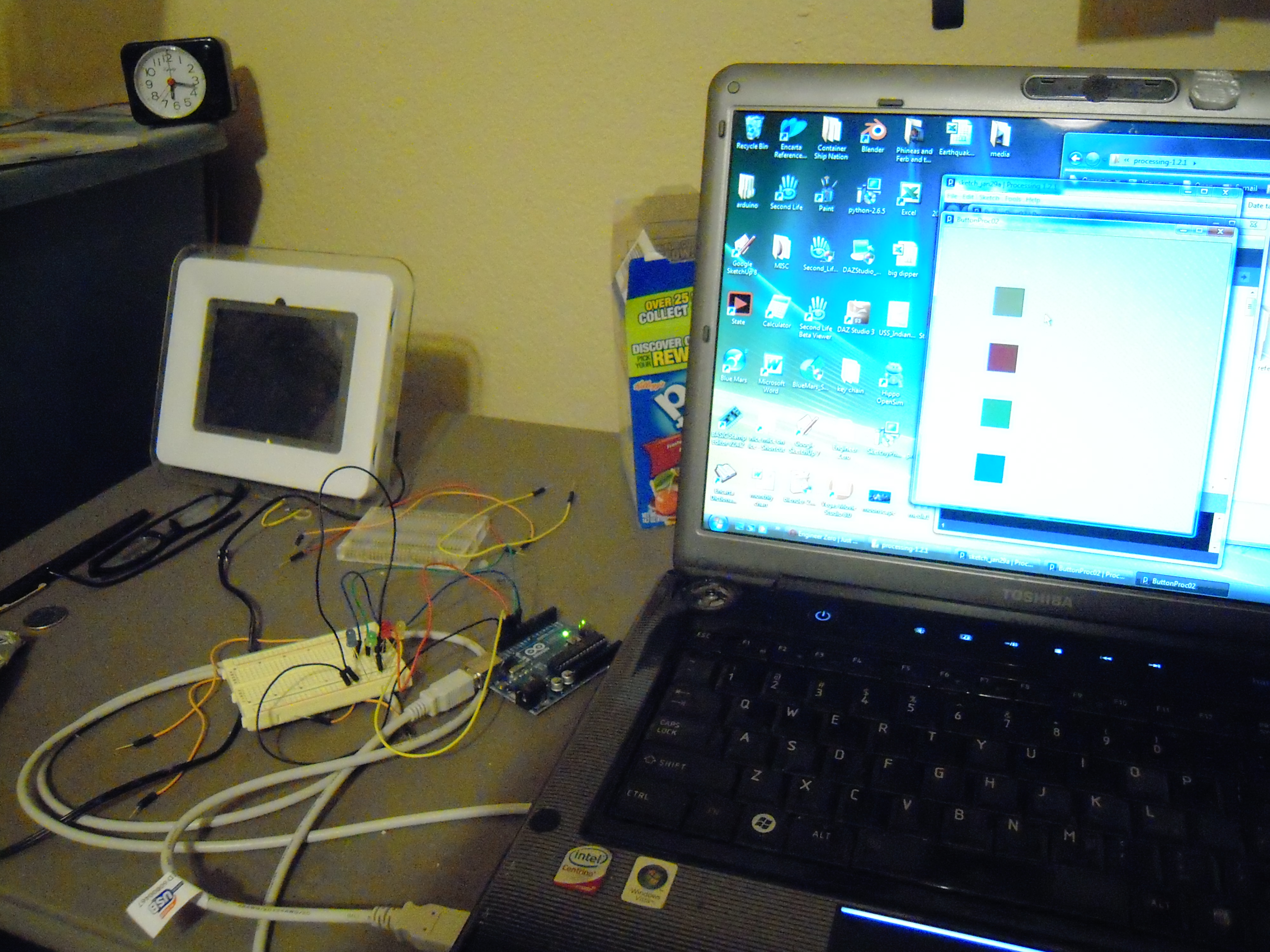
Here’s the physical layout in my elaborately equipped and tidy laboratory:
And here’s a closeup of the Arduino and the poor suffering breadboard:
BTW, the LEDs and the jumpers came from the Getting Started with Arduino kit. I’m not sure if this breadboard or the one in the background came with the kit.
Anyway, here’s the raw video:
Although not shown in the video, I can turn on more than one LED at a time, but I’m not sure that’s good for the Arduino. Haven’t burned it out yet, though!
The next step in the project is to interface the Arduino with a remote controlled toy ‘stunt’ vehicle, which coincidently has four on/off inputs. My nephew (to whom I’m assigning the designation Engineer One) needs to come over and we’re going to take it slow because I don’t want to burn out the Arduino. Which as surely as rain falls and the sun rises . . . .
BTW, I notice the diodes I downloaded from Google Sketchup 3D Warehouse look really nice, but lack a couple package details that are typically found in real-world diodes and helpfully explain to newbie electronics hobbyists (such as moi) which side is which. Hence I modified like so:
Just remember to connect ‘flatter’ and ‘shorter’ toward ground, and you too can be confident that your circuit will burn out for some other reason.
In the 1960s, the US was worried about the Missile Gap. Now we’re worried about the violinist gap?
You know what I’m talking about, it’s being hyped all over the media, there’s a Chinese-American woman who calls herself the Tiger Mom, and has written a book about how tough she is in raising her children. For example she makes them practice violin for hours every day.
This strict discipline is held up as the ‘Traditional Chinese Way’ to raise children, and is presented as an explanation as to why China is doing so well economically while the US is faltering.
Well, I have an alternate theory. China is run by engineers who invest in engineering and science infrastructure. Meanwhile, America is run by financiers and lawyers who invest in speculating over money and then fighting over it.
Hence China builds cities and America can’t fill potholes.
By the way, Tiger Mom is a law professor. She teaches financial law.
Oh, this thing has gotten out of control. Originally, I meant to have a simple blog entry with a series of Sketchup images. Then I thought about making a Youtube video.
It’s not that it takes that long, but after I finish correcting a mistake, I like to let a project sit for a while before I come back and check to make sure there aren’t any more mistakes. I’m assuming that I’m seeing more with fresh eyes and that there isn’t some quantum-physical attribute to the universe that causes mistakes to ‘grow’ in the meantime! And with this project, mistakes do seem to grow.
Anyhow, Arduino Park should be on Youtube tomorrow. And remember, Stomping Is Not Recommended.
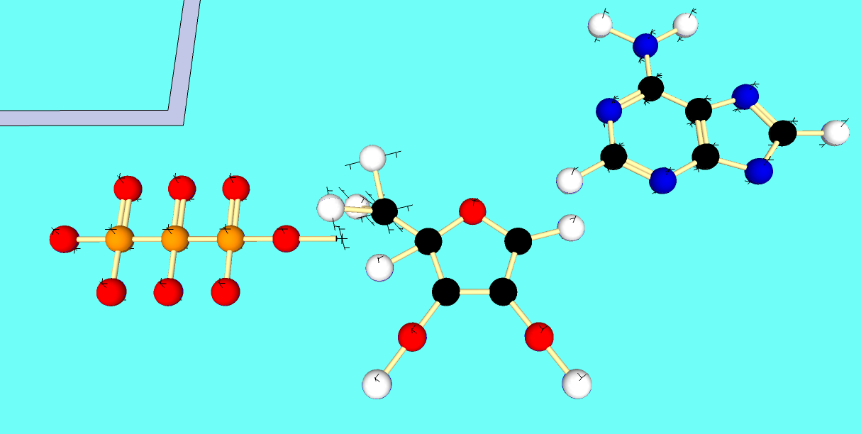
Welllll, I got all the atoms and bonds right, I think. Now the problem is the angles. Oh, and to be in the cool crowd, I’ll have to indicate somehow that the single-bonded oxygens on the phosphate chain are negatively charged.