
The OWI robotic arm has over 1100 reviews on Amazon already, so I won’t review it here. Instead, I wanted to share some tips that I learned while assembling the robot. It took me five hours — but maybe with the help of these tips, you can do it much faster!

Get a good screwdriver
There are sixty-four tiny screws in the OWI-535 kit. Holding the screwdriver, the screw, and the two parts to be attached sometimes feels like a job that requires four hands. A magnetic screwdriver will hold onto the screw and help you position it over the hole, which makes the task a lot easier.
Actually, I don’t know if the screws in the kit are attracted by magnets, but it certainly would have sped things up quite a bit if they were and if my screwdriver had been magnetic.
Also, I was using a tiny screwdriver I got from a dollar store, and that wasn’t great either. A screwdriver should have a comfortable size to fit in your hand if you’re going to be using it a lot.
Another thing you might consider is a battery powered screw driver. This will relieve a lot of the tedium and wrist/finger strain. If you do a lot of kit assembly, it’s a good investment.
***
Use a glue stick to hold the nuts in place
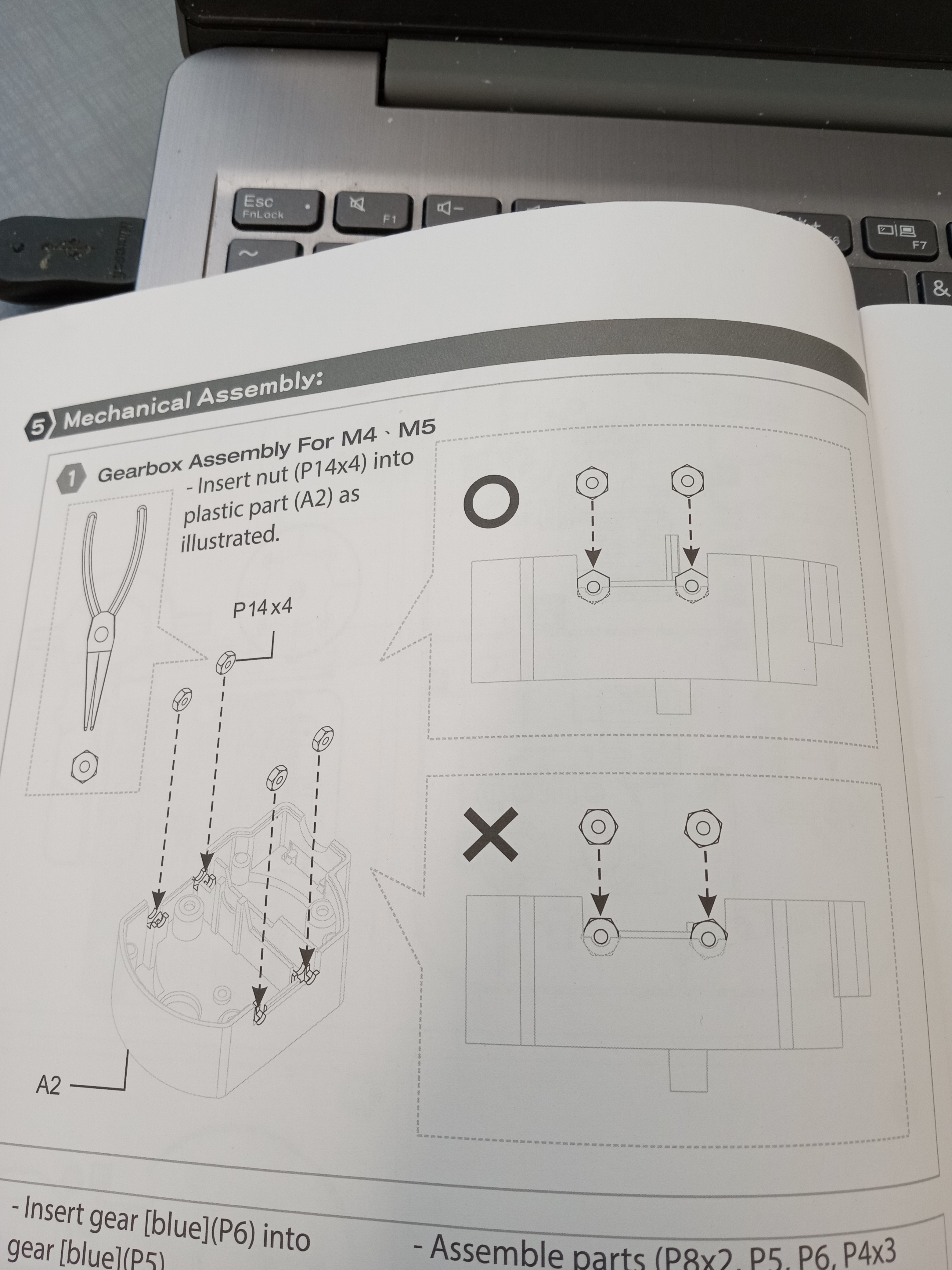
There are five motor cases in the OWI-535 kit, and they each have four screws and four nuts to attach them to the rest of the arm assembly. That’s twenty of these tiny little nuts that must be inserted in the casing slots (as shown).
Problem is, once you insert the nuts and close up the case, they have a tendency to fall out of place. This is very discouraging because you’ll need to re-open the case, and when you do that, the gears and motor will shift around and thus also need to be re-positioned. Then you close the case and . . . same thing over and over.
However, I found that if I rubbed a glue stick onto the nuts, the glue would keep the nuts in place long enough to fasten the bolts. We’re not talking superglue here, just a regular old glue stick. I wasted an hour on positioning and repositioning the nuts in just the first case before I learned this trick, and I doubt that I would have been able to finish the entire assembly at all without doing this.
***
Pay attention to how the parts are positioned according to the manual

The above illustration in the OWI-535 assembly instructions pamphlet shows that the two claws of the gripper need to be spread apart an equal distance so that they will come together in the center. So I thought, why not assemble them so that they are already touching in the middle? Well, if you do that, you won’t be able to install the light that goes between them.
(You may notice from the photo that I didn’t get around to installing the light or the hood on the gripper, btw.)
A similar issue happened when I didn’t have the arm in the same pose as the illustration in the assembly instructions, and that created problems in being able to fit parts together.
The instructions don’t specifically tell you that you must assemble the arm in the poses shown in the illustrations, but it’s a good idea.
***
Random Meta Stuff
You might be thinking, “Why not just get a servo arm and forget all this business of gears and complex wiring?” Well, that works with big servos, but those robot arms are more expensive. As for the 9g micro-servos, I’m not so sure they have enough power to lift even themselves. I may be wrong on that, but I did assemble a micro-servo arm before this and the motor action was woefully feeble. So there’s a reason this kit is so popular.
It helps to know the big picture so that you don’t get discouraged somewhere in the middle. So just what are you doing? You’re putting five motors in cases with gears that trade off rotational speed for torque. Then you’re attaching the motor cases so that one motor each operates the gripper, the wrist, the elbow, the base up-and-down, and the base rotation. Then you’re connecting the battery and the wires of the motors to the control box. Finally, you assemble the levers and electrical contacts of the control box. And you’re done!
And everything is held together by screws. Lots of screws.
Highly recommended that you read the instructions at least once. The more you know what you’re doing, the more confidence you ‘ll have, and the faster you’ll get it done with fewer errors.
Well, I hope this helps and that you are able to avoid frustration and have fun while assembling your OWI-535 “Edge” arm — and I especially hope that it works!
If you have any tips of your own, please leave a comment. Thanks!
As for me, in the near future I intend to hack the arm to put it under the control of an arduino. If that sounds interesting, I hope you’ll check back.

Pingback: DC Motor Control: H-Bridge and L293D chip | Engineer Zero