Test Box Pattern for Laser Cutting

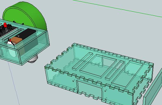
Before I try to cut for an entire robot, I thought I’d try a ‘test box.’ This is an object that has no functional value, but will give me an idea of how slots and tabs fit together in laser-cut acrylic, what size holes I need for the standoffs, etc.

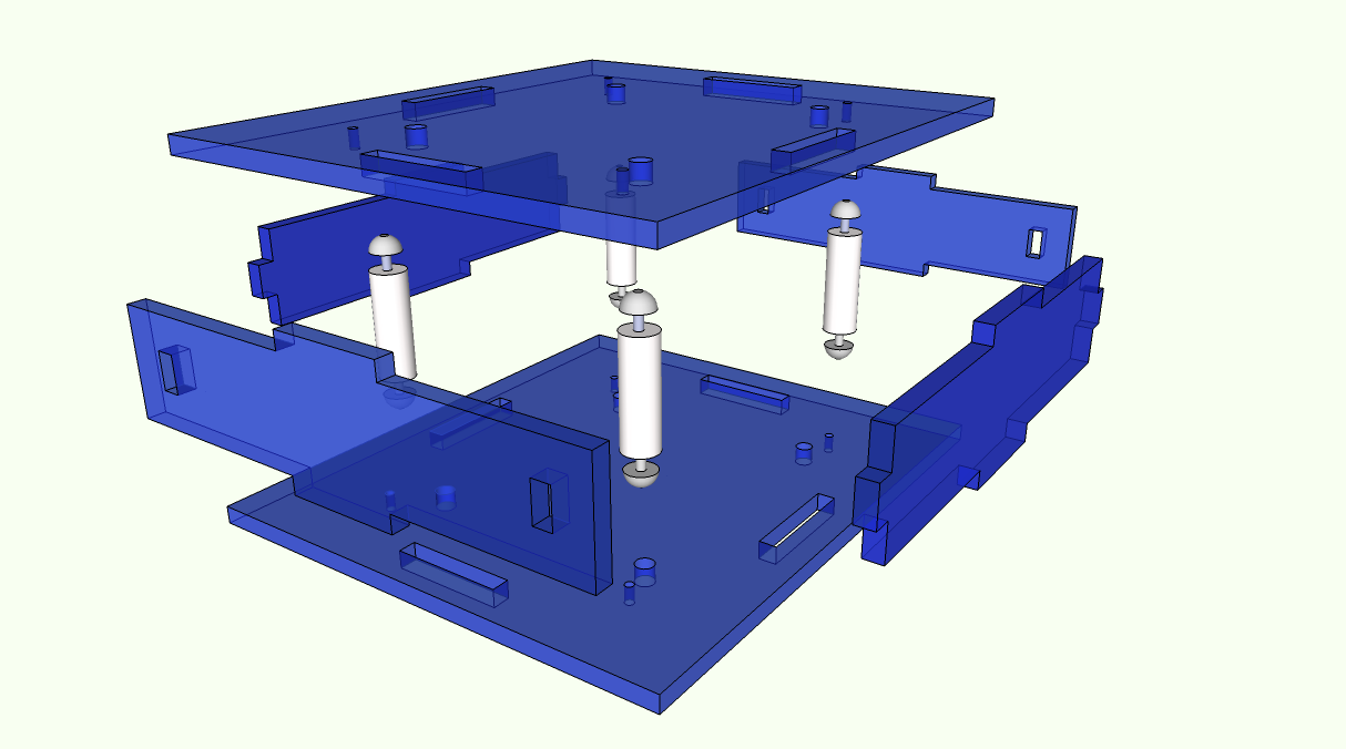
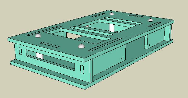
Here’s the test box design that I came up with:

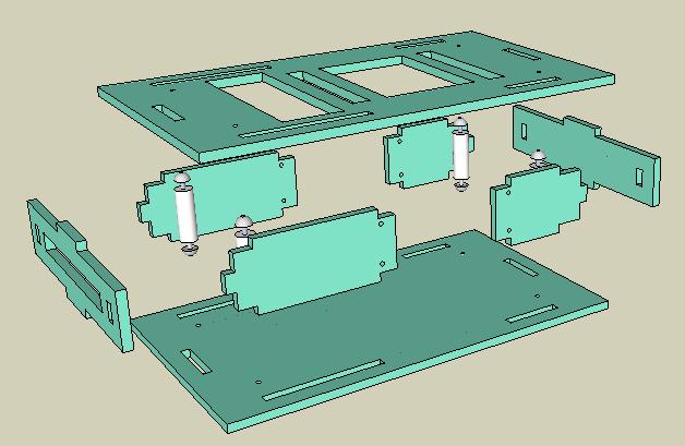
This is how the pieces fit together:

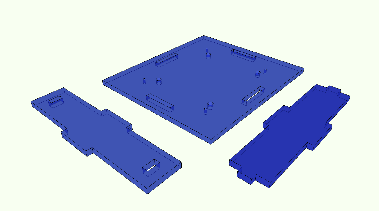
There are six pieces, but each is a duplicate:

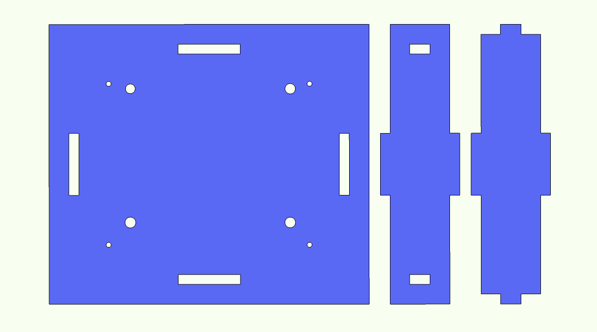
And finally this is what I’ll be importing into Inkscape:

And ascertaining the viability of export/import of the pattern from Sketchup to Inkscape will be another thing that the test box is for. Here’s the Youtube video from Richard showing how that is supposed to work:

Posted in Uncategorized | Tagged , , , , | Leave a comment

Grisbot color options

Acrylic can really look nice, and who knows, I may want to offer different colors. I’m not exactly in the position of Henry Ford, who told his customers they could have a car in any color they wanted so long as it was black.

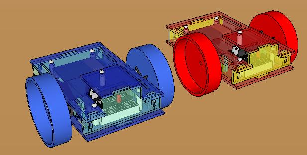
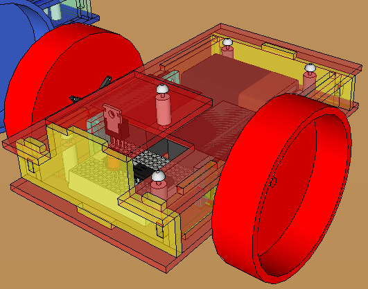
I switched out the iced tea jar wheels for peanut butter jar wheels, which are somewhat smaller and come in ‘tealish’ and red as shown. The red and gold model reminds me of a Chinese New Year’s dragon.

It might be cool to have LED running lights, though that would take up inputs. Well, maybe I can offer that as an option.

Not yet shown are the sensors, which will affect how the front piece is cut.

Posted in Uncategorized | Tagged , , , , , | Leave a comment

Split Level Standoffs

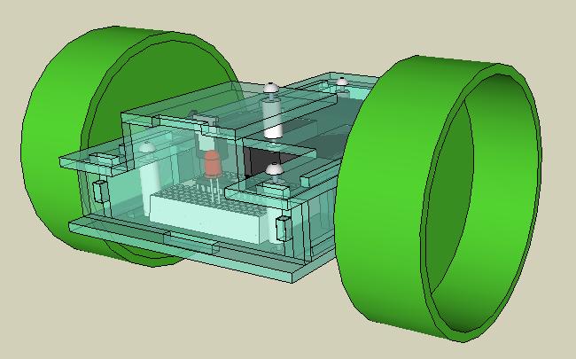
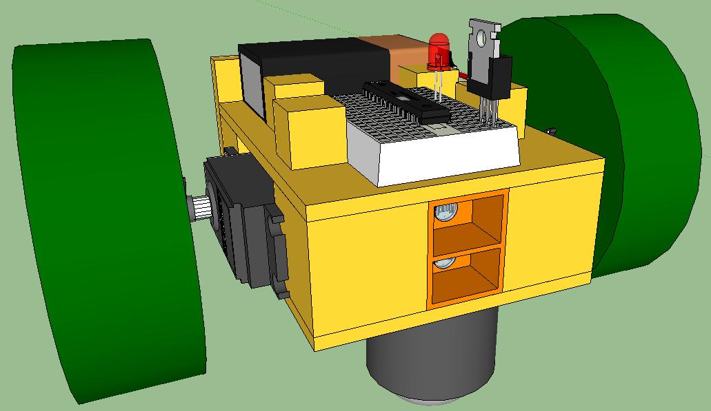
The full title of this post would be something like ‘Split Level Standoff Laser Cut Acrylic Casing for Robot.’ Anyhow, I added a level by using another standoff. This was necessary because the voltage regulator is too tall to fit inside the original casing with the 3/4 inch standoffs.

Tomorrow I think I’ll play around with colors and tints, and maybe use smaller wheels.

Posted in Uncategorized | Tagged , , , , , | Leave a comment

Laser cut acrylic robot casing with standoffs

Recently, Maker Shed offered a laser-cut acrylic casing for a geiger counter. Here is a blog entry on the assembly of the casing, which shows how standoffs are used.

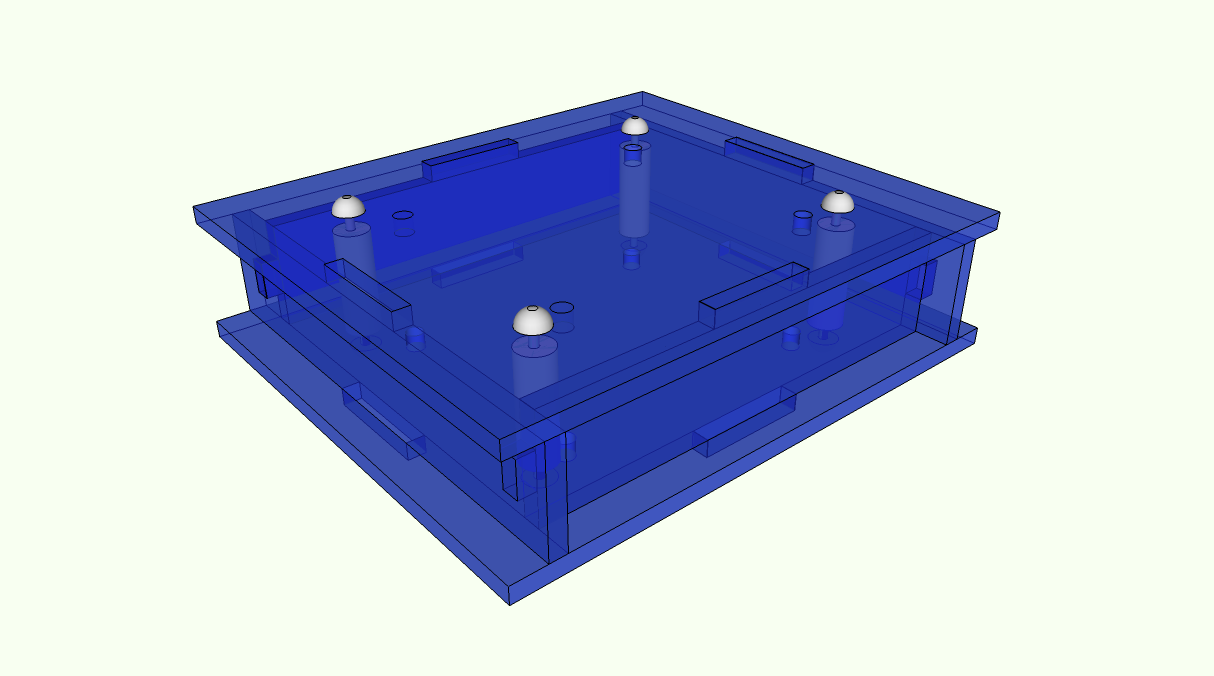
I thought, “That looks nice,” so it was back to the drawing board. I got the dimensions and pricing for standoffs here, and after some fiddling around in Sketchup, I constructed a laser-cut acrylic robot casing with standoffs like so:

(I’ve reduced the transparency to zero for clarity’s sake.)

And this is what it looks like in an exploded view:

So we’ve gone from acetone-bonding, to bolts, to standoffs. It looks like the design is beginning to stabilize. I think for sure that this week I’ll be cutting acrylic.

Posted in Uncategorized | Tagged , , , , , | Leave a comment

Bolting Laser Bots

Okay, the title is a little bit of a joke, but this is a continuation of my efforts yesterday to conceptualize how laser-cut acrylic pieces can be assembled into a box-like enclosure for a robot.

Since the pieces have been modified since yesterday, I’ll first show what they look like now:
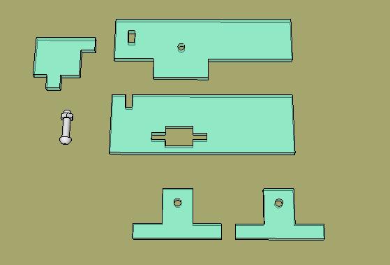
I revised the slot in the bottom piece so that it would accomodate a wider tab in the middle. I also added the back piece, which is shown on the left. (actually, only half of the back piece is shown, but there’s method to my madness.)
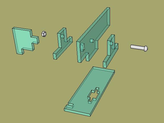
And that is the exploded view, which I’ll now compress like so:

Of course, that’s only for one corner. For the entire box:
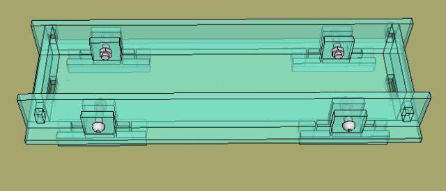
Now, this is not something that I’m going to physically build. I just wanted to work out in my mind what I need to do in order to make a boxlike casing that is composed of laser cut acrylic pieces bolted together. Once I’m satisfied that I have a workable design, I’ll modify it to enclose the robot and then that version will be cut and assembled.

I think I still have some things to think about yet, but it looks like it’s getting there.

Tomorrow I think I’ll make some test pieces that I can take to the laser cutter to see how they work out. I’m worried that the Sketchup-to-Inkscape export/import process is not robust, and even if it was, I’d still have trouble fitting a 1/8″ tab into a 1/8″ slot. I don’t have a good feeling about success on the first try, so my attitude for Saturday is: it’s going to be a learning experience.
Posted in Uncategorized | Tagged , , , , , | Leave a comment

Bolting Together Laser Cut Parts

Plan A was to use acetone to bond the parts of the robot’s laser-cut casing together. However, the overarching goal is to make a kit that can be sold to kids, and it occurs to me that having ‘Buy acetone’ as the first step isn’t going to increase the popularity of the kit with kids or their parents.

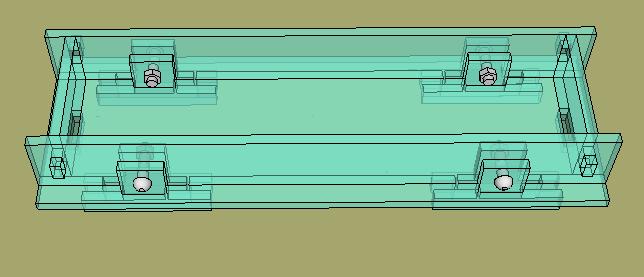
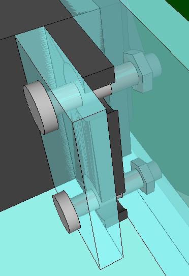
Plan B therefore is to join the perpendicular sides with bolts, which require only a screw driver. I think I’ve come up with a way to do this. Here’s how a corner would look:

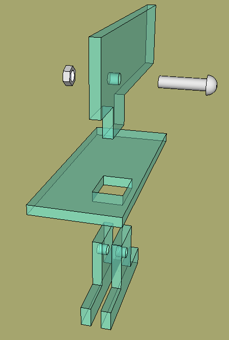
Here’s the exploded view of the pieces (bolt and nut threads not shown):

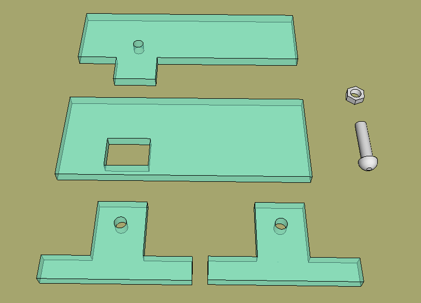
And here are the pieces laid out:

I hope I can get away with just four bolts, one in each corner on the bottom. Meanwhile, the top is just going to be a lid and the front and back will be locked into place with tabs and slots into the other sides.

I’ll look into that design configuration tomorrow.

Posted in Uncategorized | Tagged , , , , | Leave a comment

Crenellated Laser Cut Patterns for Grisbot in Sketchup

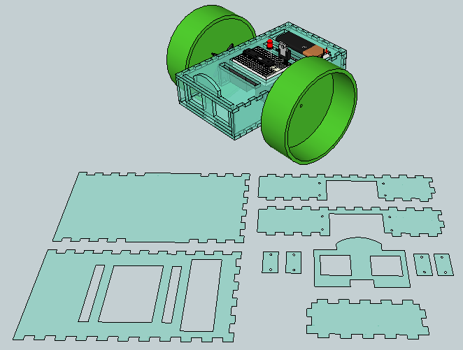
After much tweaking, I seem to have crenellated patterns for Grisbot that look like they just might print out on a laser cutter.

How do you go from a 3D side to a 2D pattern in Sketchup? Well, it’s not that big a deal to begin with because of course the sides are only an eighth of an inch thick. But the laser cutter cuts in 2D, so even an eighth of an inch is a distraction.

The solution is to click just on the top or outer surface of each side, then select copy, then paste. I’ll assume you know how to get in and out of groups in Sketchup.

(Perhaps to belabor the obvious: although the laser cutter only cares about 2D patterns, the outputted physical pieces will be 1/8 inch thick because the acrylic sheet upon which the pattern is being cut is 1/8 inch thick.)

I’ve never worked with a laser cutter before, but I talked to someone at StudentRND about a month or so ago, and he said it was possible to use Sketchup to create patterns for their cutter. I may need some kind of plug-in, however. We shall see.

StudentRND is open tomorrow afternoon, so that’s when I’ll drop by and see if everything I’ve done so far is garbage, or if it is salvageable, or if miracle of miracles I got it right the first time.

(Notice that I’m using the 2-Ls spelling for crenellated today, despite flagging by the Word Press spell checker. According to Google, 2-Ls has four times more hits than 1-L. So I’m going with the herd on this one.)

Posted in Uncategorized | Tagged , , , , , | 1 Comment

Crenelating laser-cut acrylic robot casings

How do you get two pieces of laser-cut acrylic to join at right angles? One solution is to glue them together using crenelations at the edges to increase the joint strength.

Crenelations are what they call the pattern on top of European castle walls. Crenels are the cuts, merlons are the teeth, and if you want to learn more, see wikipedia here. (I note that wikipedia spells crenelation with two L’s, but the WordPress spell-checker prefers only one.)

There’s information about how to glue crenelated laser-cut acrylic boxes together with acetone at the Curious Inventor Blog.

As you can see in the above illustration, I’m adapting my Sketchup design of an acrylic robot casing to add crenelations so that it can be glued. I’m still partial to just bolting the sides together, but I wanted to explore the options.

And yes, I had fun thinking up the title for this entry.

Posted in Uncategorized | Tagged , , , , , , , | Leave a comment

Grisbot in Acrylic

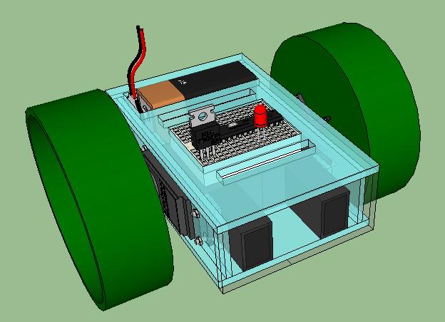
Here’s Grisbot in baby-blue acrylic. I was hoping to laser-cut it tonight at StudentRND but after getting into the design work I realize that I probably won’t be ready until next week at the earliest. At any rate, at least I can show it off in Sketchup.

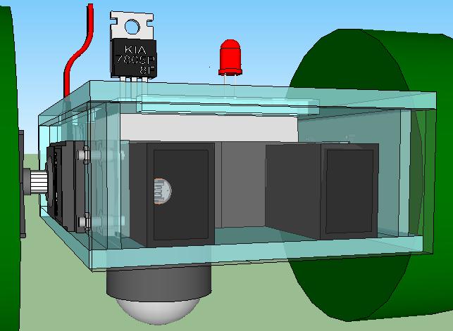
A frontal view. The front side will be clear but is tinted gray here so that it can seen. Notice the empty space in the middle. Maybe I can expand the cowlings for the photosensors.

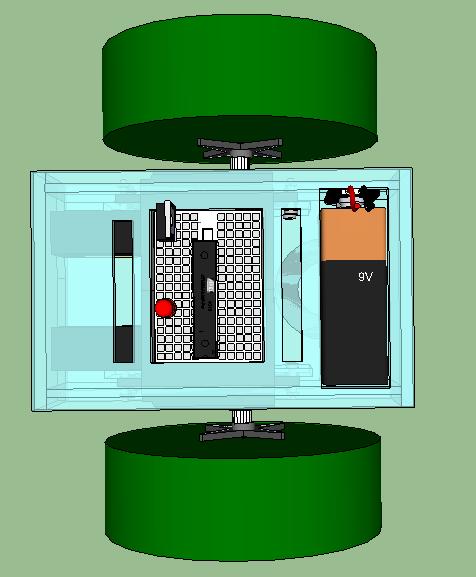
Overhead view shows the many openings that will have to be cut. And I still haven’t put in the tabs and brace holes!

Here is my “plan” for securing the servos to the chassis. I have no experience assembling things, and perhaps it shows. The bolt heads by the way are curved and 4-ply but I didn’t see the value in going into that level of detail.

I think I need to add L-shaped braces between the bottom and the sides here too. Tomorrow.

Posted in Uncategorized | Tagged , , , | Leave a comment

Grisbot II design

This is a double-decker design which:

(1) secures the servos to the chassis (with bolts/screws not shown)

(2) renders the breadboard more accessible

(3) uses dual sensors

This one probably won’t be built, but it’s on the way to something that will be.

(NOT SHOWN: reed switch mounted at top, far end.)

Posted in Uncategorized | Tagged , , , | Leave a comment