
As you recall, I’m working on an electronic nonlethal mouse trap.

To avoid wasting battery power, the mouse trap is in standby until the mouse pushes open the one-way door.


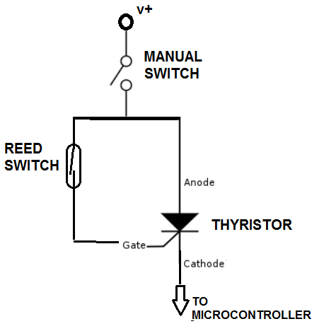
I needed a circuit that would turn on when a magnetic field is applied to a reed switch, then stay on even after the field is removed. Based on an internet search, a thyristor appeared to be the ideal component. More specifically, I needed a type of thyristor known as a TRIAC.
But would that actually work? I designed a simple circuit schematic to test a TRIAC/Reed switch combination:
After a quick trip to Vetco, I got a TRIAC (NTE 5600) and built the circuit as follows:

In theory, when the magnetic is applied to the reed switch, the TRIAC gate will be powered and current will flow through the TRIAC to the LED, which will light. When the magnet is removed, the TRIAC will remain active and the LED will continue to glow until power is removed from the circuit.
So here’s the test:
Yea, it works! So the electronic nonlethal mouse trap comes a step closer to realization.
