
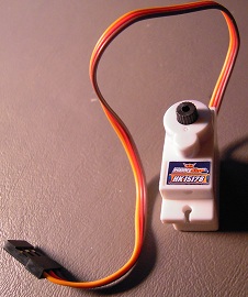
Say you want to build a small robot, but you soon discover that DC motors move too fast and geared DC motors are too expensive. Then you hear about servos. Servos are basically geared DC motors, and microservos seem just the right size for your robot.
So you attach a couple to your wheels and . . . the wheels move about half a turn and stop.
What gives? Your microservos probably have a fixed sweep angle. They need to be ‘converted’ to continuous rotation. This blog entry will describe how to do that. I’ve tried this procedure on several brands, and they seem to be the same.
You’ll need:
*a tiny screw driver
*a 1/16″ drill bit
*wire clippers
*glue
*prying tool
*needle-nosed pliers
*emery board
*Arduino.
In each of the following steps, I focus on doing and not explaining. Explaining is good too, but perhaps another blog entry, another day.
It only takes a few minutes to convert a micro servo, but I recommend reading all the steps before starting.
1. Open the servo.
Use your tiny screwdriver to unscrew the tiny bolts from the bottom of the servo. You don’t have to pull the bolts all the way out.
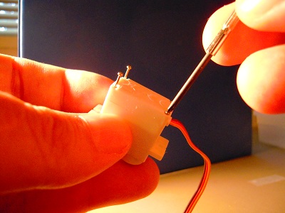
You just need to pull the bolts out far enough to pull off the top of the servo, which you will set aside for now.

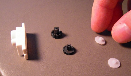
2. Remove the gears.
GENTLY pry the gears off the servo.

Keep track of the order and position so you can put them back the same way later.

3. Connect the servo to an Arduino.
The red line goes to the 5v header hole, the brown (or black) to the ground header. The remaining line (often yellow or white) goes to pin 10.

4. Program the Arduino to center the servo at 90 degrees.
Copy and paste this code into your Arduino IDE:
//servo 90

#include<Servo.h>

Servo myservo;

void setup(){
myservo.attach(10);
}

void loop(){
myservo.write(90);
}
Send it over to the Arduino. BE PREPARED: The servo will start whirring!

5. Center the servo.
See the potentiometer shaft?
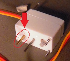
Slowly twist it clockwise and counter-clockwise GENTLY. The motor will whir rapidly, then slow down, then speed up again. Adjust the shaft so that the motor either stops or goes as slow as possible.

6. Glue the shaft in place.
Detach the servo from the Arduino. Glue the base of the potentiometer shaft so that it will no longer be able to turn from the 90 degree position. You’ll want to keep the servo oriented so that the glue doesn’t run.

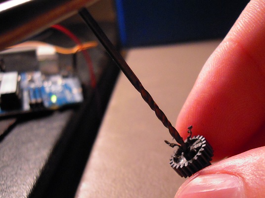
7. Remove the gear stops.
Get the big potentiometer shaft gear.

See the little nubs on the bottom of the big gear?

Snip them off with the clippers.

To ensure that nothing remains to stick out from the gear base, you may want to use an emery board to rub the stubs of the nubs. (Sorry for the Dr. Seuss rhyming, it was unavoidable.)


8. Widen gear holes.
Again, take the big gear that goes on the potentiometer shaft. Stick the drill bit into the hole, and twist it through, widening the hole.


Obtain the other potentiometer shaft gear.
And now widen the hole for the other gear, like so:

9. Wait for the glue to dry.

10. Test the servo.
Reconnect the servo to the Arduino as before. Try different angle values in the myservo.write() command: 90, 0, and 180. The servo should stop or move slowly, then move fast in one direction and then fast in the other.
Here, as a visual aid, is the same photo of the setup that I used before:
11. Put the gears back on.
Which will be easy because you remembered to keep them in the proper order.
12. Close ‘er up.
Here’s the same picture I used in Step #2. Imagine I’m twisting the screwdriver the other way:
And this looks familiar too.
13. Repeat with the other servo.
Because there are two servos per robot, one for the left wheel and one for the right wheel:

14. Congratulate yourself.
Armed with the knowledge of micro servo conversion, you can now build an army of tiny robots and conquer an entire table top in a matter of minutes. Good luck, Commander!


Thank you! I look forward to popping open servos.